USA 16411
UNITED STATES PATENT OFFICE.
ALFRED TONKS, OF BOSTON, MASSACHUSETTS.
IMPROVEMENT IN LOCKS OF FIRE-ARMS.
Specification forming part of Letters Patent No. 16,411, dated January 13, 1857.
To all whom it may concern:
Be it known that I, Alfred Tonks, of Boston, in the county of Suffolk and State of Massachusetts, have invented an Improvement in the Locks of Fire-Arms; and I do hereby declare that the same is fully described and represented in the following specification and the accompanying drawings, of which—
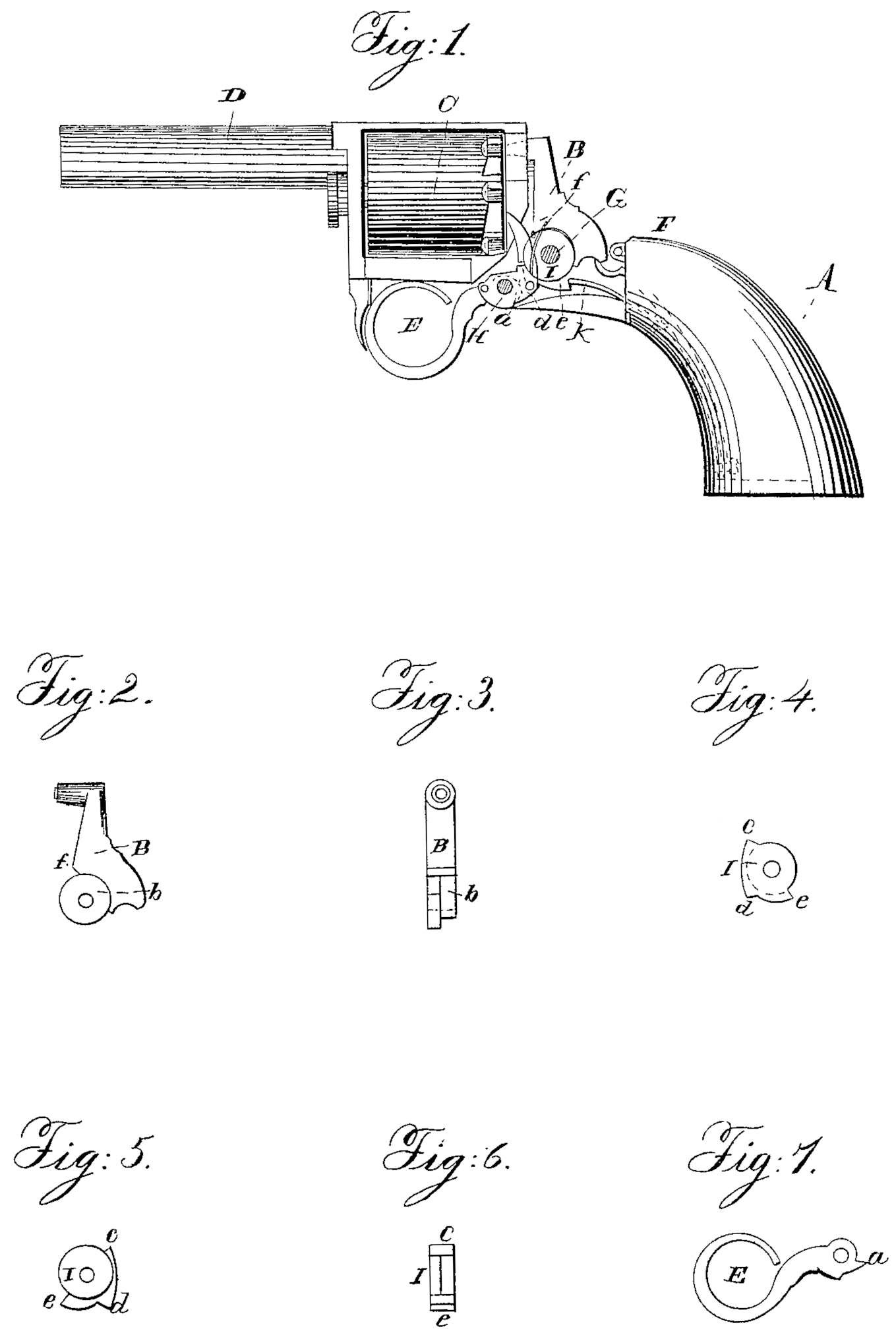
Figure 1 shows a revolver or pistol fitted with my improvement in its lock, the side plate of the lock being removed in order to exhibit the internal arrangement and parts of the lock. Fig. 2 is a side view of the striker or hammer as detached from its arbor. Fig. 3 is a front edge view of the same. Figs. 4, 5, and 6 are front, rear, and edge views of the spring rocker-catch, to be hereinafter described. Fig. 7 is a side view of the trigger.
In these drawings, A denotes the stock-frame or handle of the pistol; B, the striker or percussion-hammer; C, the rotary chambered cylinder; D, the barrel; E, the trigger; F, the mainspring; G, the arbor of the striker, and H the arbor of the trigger, the two arbors being screw-pins extended through one and into the other plate of the lock-case.
The trigger I form with a small angular projection, a, arranged on it as shown in the drawings. This is to operate in connection with a rotary or rocker catch, I, which is placed and turns freely on the arbor G and within a recess, b, formed in the lower part of the striker, as shown in Figs. 2 and 3. This rotary catch is constructed with three shoulders or angular teeth, c d e. The upper one, c, brings up against a bearing or shoulder,f, formed on the striker or at the upper part of its recess, as shown in the drawings. The tooth d works in connection with the tooth a of the trigger, a spring, K, being employed to press upon the tooth e, as shown in Fig. 1.
For rotating the chambered cylinder I employ an impelling-pawl, geared to the trigger, and arranged as shown by red lines in Fig. 1.
When the trigger is retracted the tooth a will be borne against the tooth d, so as to crowd the tooth c against the shoulder f. By continuing to retract the trigger the striker will be raised off the nipple until the tooth a passes by the tooth d, when the striker will be set free, and by the mainspring it will be thrown smartly toward the nipple.
During the forward or return movement of the trigger the spring K will allow the catch I to move under the back-pressure of the tooth a until the said tooth passes by the tooth d. As soon as this takes place the spring K will restore the catch I, or so move it as to bring its tooth c up against the shoulder f, the catch thereby being brought back to a proper position for the trigger to operate on it and raise the striker whenever such trigger is next pulled backward.
The advantages of this construction of a lock are that it admits of great compactness of the collection of working parts. It enables the striker to be arranged vertically. It has the merit of durability, and is little liable to get out of order or repair, and, besides, it works truly and with ease. If desirable, the trigger may have a spring for throwing it forward after release of the finger or retractile power from it.
I do not claim raising the striker by a spring-latch hinged to the trigger, such latch being disengaged from the striker by means of a cam on one or the other of them; but
What I do claim is—
The above-described arrangement or application of the spring rocker-catch, the tooth a of the trigger, and the shoulder f with respect to the striker, its arbor, and the trigger, and so as to enable the striker to be operated substantially as specified.
In testimony whereof I have hereunto set my signature this 24th day of November, A.D. 1856.
ALEFRIED TONKS
Witnesses:
R. H. Eddy,
F. P. Hale, Jr.

