US 9701
UNITED STATES PATENT OFFICE.
CHAS. N. TYLER, OF WORCESTER, MASSACHUSETTS.
IMPROVEMENT IN REPEATING FIRE ARMS.
Specification forming part of Letters Patent No. 9770, dated May 3, 1853.
To all whom it may concern:
Be it known that I, CHARLES N. TYLER, of Worcester, in the county of Worcester and State of Massachusetts, have invented certain new and useful Improvements in Repeating Fire-Arms; and I do hereby declare that the following is a full, clear, and exact description of the same, reference being had to the accompanying drawings, forming part of this specification, in which—
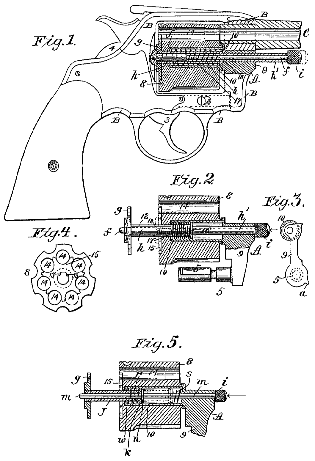
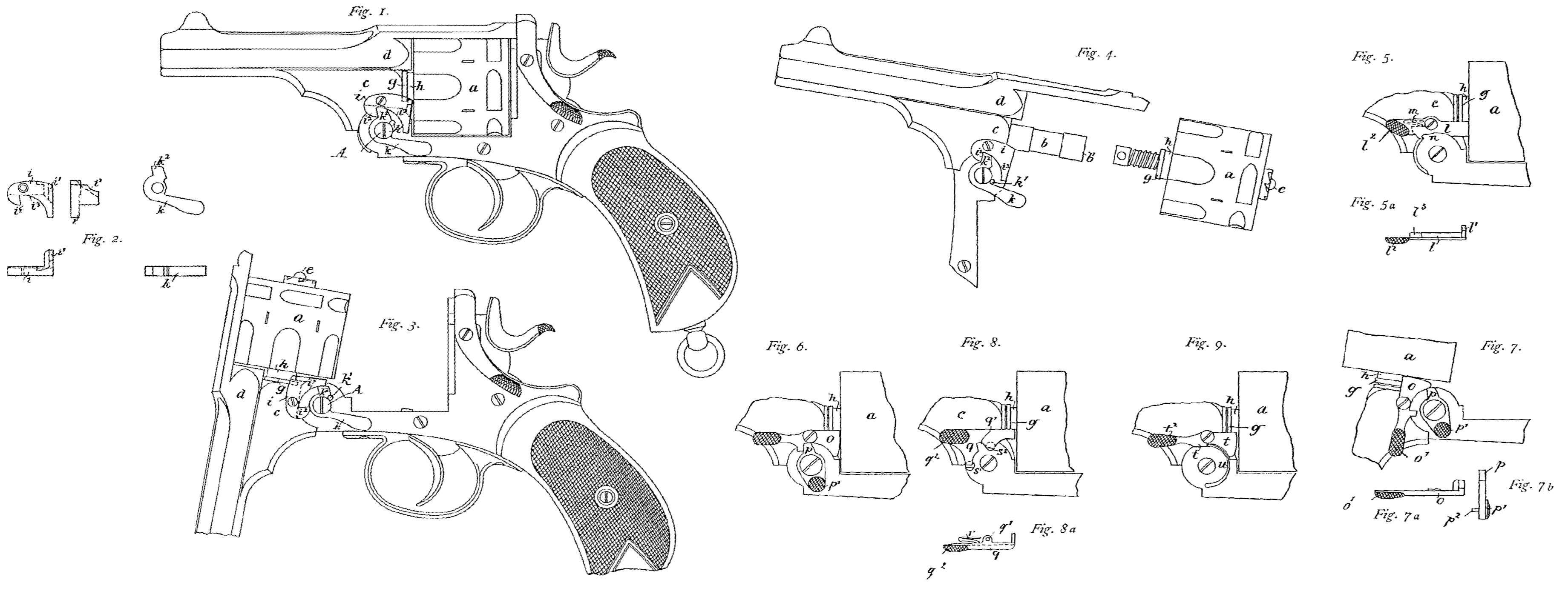
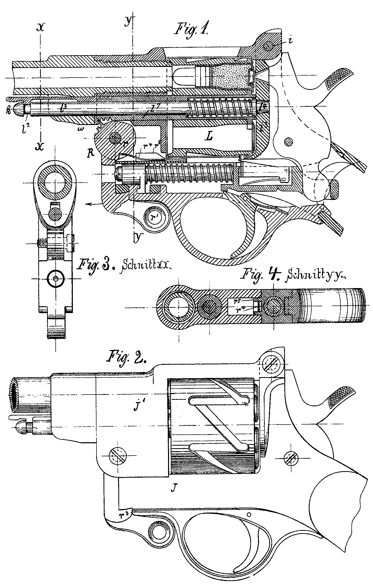
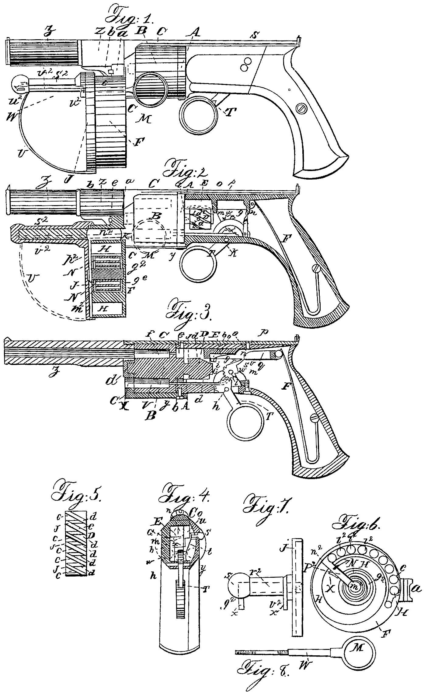
Figure 1 is a side view of a pistol constructed according to my improvements, the parts being in their position after discharging. Fig. 2 is a similar view having one side of the stock removed to show the lock, and the charger shown in section. Fig. 3 is a section through the center, showing the position of the parts when the pistol is cocked or ready for dis charging. Fig. 4 is a transverse Section of breech and lock, Fig. 5 is a projection on a plane of the grooved cylinder at the back of the rotating breech. Fig. 6 is a view of the charger with its cap removed. Fig. 7 is a side view of the cap of the charger. Fig. 8 represents a view of the finger-rod by which the cartridge is transferred from the charger into the breech.
Similar letters of reference indicate corresponding parts in each of the several figures.
The principal object of these improvements is to bring the whole of the lock, including the hammer or driver, but excepting the trigger, into a space sufficiently small to be contained within the stock, and thus offering no obstruction to the sight, and without increasing its size, so as to make it cumbrous or inconvenient, and at the same time to produce an arm as sure in its operation and as free from liability to accidental discharge as any in use.
The first improvement relates to certain means through which the trigger acts upon the hammer or driver for the purpose of cocking and discharging, whereby the piece is cocked by drawing back the trigger, and after ward may be uncocked by simply moving the trigger forward.
The second improvement consists in a spring stop, which is acted upon by a small button protruding from the stock at a convenient point to be pressed upon by the thumb or finger, for the purpose of preventing the possibility of overdrawing the trigger and accidentally discharging the piece in cocking.
The third improvement consists in a charger attached to the barrel in front of the breech, and which may contain thirty cartridges, more or less, that may be transferred, one at a time, into the chamber of the breech by simply pulling a rod with one finger, while with an other the breech is rotated and the hammer cocked and tipped and the charge fired.
To enable those skilled in the art to make and to use my invention, I will proceed to de scribe fully its construction and operation.
The pistol shown in the drawings is for cartridges which are exploded by pricking, but the improvements are equally applicable when the chambers are loaded with loose powder to be exploded by caps.
The stock is made with the middle part of metal, as being more suitable to admit of a larger space within, its front end terminating in a disk, A of corresponding diameter with the rotating chambered breech B. The barrel is secured to the breech by a steel strap, C, screwed to the latter by screws above and be low. The breech fits closely between the front of the strap C and the disk A, having a jour nal, a, in front fitting a bearing in the strap, and another, b, at the back fitting a bearing in the disk A. The breech has six chambers and is made solid, and at the back of the journal b, forming one piece with the breech, there is a small cylinder, D, having six spiral grooves, c c, at equal distances apart and parallel with each other, being of equal depth along their whole length, except that at each end there is a slight inclination toward the axis. The number of these grooves corresponds always with the number of chambers.
The spiral grooves are connected with each other by means of grooves d d, which are parallel with the axis of the cylinder, the latter grooves, d, being rather deeper than the spiral groove c at their back ends, but inclining up ward almost to the periphery of the cylinder at their front ends, forming a step, j, at the point of connection with the front end of each spiral groove.
E is the driver, which is a square steel bar sliding in guides, which keep it in a line with the barrel. It is driven forward by a spring, F, acting on its back end when not drawn back by the trigger, and passes through an opening, e, in the disk A, being furnished at its front end with a needle to enter the vent f at the back of the uppermost chamber, or that in line with the barrel. There is a recess, g, in the driver, in which a spring, h, is secured, carrying at its front end a stud, i, which works in the grooves of the cylinder D. The tendency of the spring is to force the stud to the bottom of the groove.
The movement of the driver and the length of the cylinder bear such relation to each other that the stud i passes, and when the breech is stationary with a chamber in line with the barrel the uppermost of the straight grooves d is always in line with the driver. When the driver is drawn back to cock the piece, the stud i, being prevented by the step j from entering the straight groove, enters the spiral groove c connecting with it, and in moving along it turns the cylinder and breech the required distance, bringing the next straight groove in line with the driver. On the return of the driver in firing, the stud passes along the straight groove, and therefore does not move the breech.
T is the trigger, which works on a pivot, k, and acts upon the driver through a toothed segment at its upper end, operating on another toothed segment, G, turning on a pivot, l, and carrying a tongue, m, whose point acts upon a Small jack, n, hanging on a pivot, o, in a slot within the driver. The upper or back part of the jack catches under a small pin, p, placed across the slot in the driver, and causes it to be held stationary when the tongue m presses. against its front or lower end. A spring, q, is also applied to it for the purpose of holding it in a position for the tongue to act upon it; but this spring will yield and allow it to move When it is necessary for the tongue to pass the jack after firing previous to recocking. The hammer is drawn back or cocked by drawing back the trigger and pressing the tongue against the jack n, the cocking being caused by the point of the tongue entering into a small notch, r, near the point of the jack, and thus forming a direct line bearing between the pivot l in the segment and the pin p in the driver, which balance may be thrown off by the slightest movement of the trigger either way, consequently a discharge or an uncocking of the piece. The discharge is caused by the point of the tongue leaving the notch r and passing the point of the jack. The driver is then left free to be driven forward by the spring F.
The stops, by which the cocking is insured, is shown best in Fig. 4, and is also shown in section in Fig. 3, where its operation will be best seen. It consists, simply, of a small flat piece of steel attached to a spring, t, whose tendency is to throw it out of operation or away from the driver toward the left-hand side of the stock, which is to the right hand of Fig. 4. The stud or button S, by which it is thrown in operation, protrudes slightly through the side of the stock, and is always, except when pressure is applied externally, forced outward by a spring, at, inside. (See Fig. 4.) When the stud S is pushed inward the stop s is thrown under the driver, where it rests against one of the guides v of the driver or against a suitable rest. The driver moves back just at the moment the point of the tongue m falls into the notch r near the point of the jack. The point of the jack, which hangs slightly below the driver, comes in contact with the stop s, and is prevented moving farther back, stop ping the driver. The point of the tongue m can not clear the point of the jack until the stop s is allowed to move away by removing the pressure from the outside of the stud, and thus letting the spring t throw it aside, when by the farther drawing back of the trigger the point of the tongue is made to clear the jack. After the discharge, the trigger, being left free, allows the tongue m to be thrown forward ready for the next discharge by a spring, w, acting upon the stud a on the side of the segment G, which also moves the trigger forward. The point of the jack is allowed to move for Ward for the point of the tongue to pass in advance of it by the spring q.
The breech is held firm in its place during the discharge by a stop-pin, y, attached to the trigger, which passes through a hole in the disk A and enters the vent of the lower chain ber. The piece may be uncocked without dis charging by moving the trigger forward, which withdraws the point of the tongue m from the notch r in the jack, and if the trigger is only allowed to move gradually the driver may be so slowly brought forward as to cause no danger of explosion.
The firing may be repeated rapidly without cocking, if desired, by simply pulling the trigger the whole distance at once.
When caps are used, instead of perforating the cartridge, the only difference in the construction will be to have suitable recesses for the nipples at the back of the breech and to make the point of the driver or hammer of suitable form.
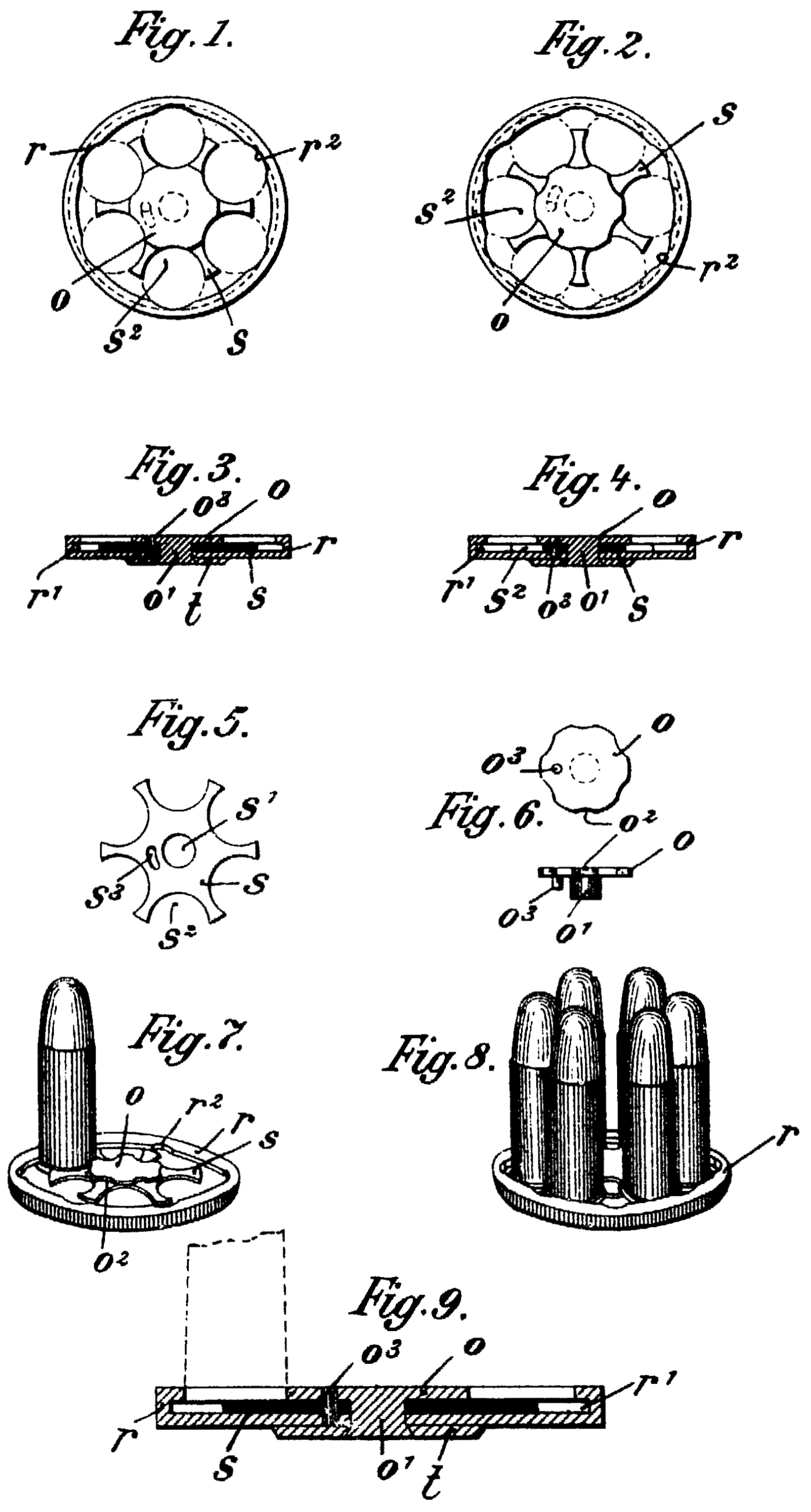
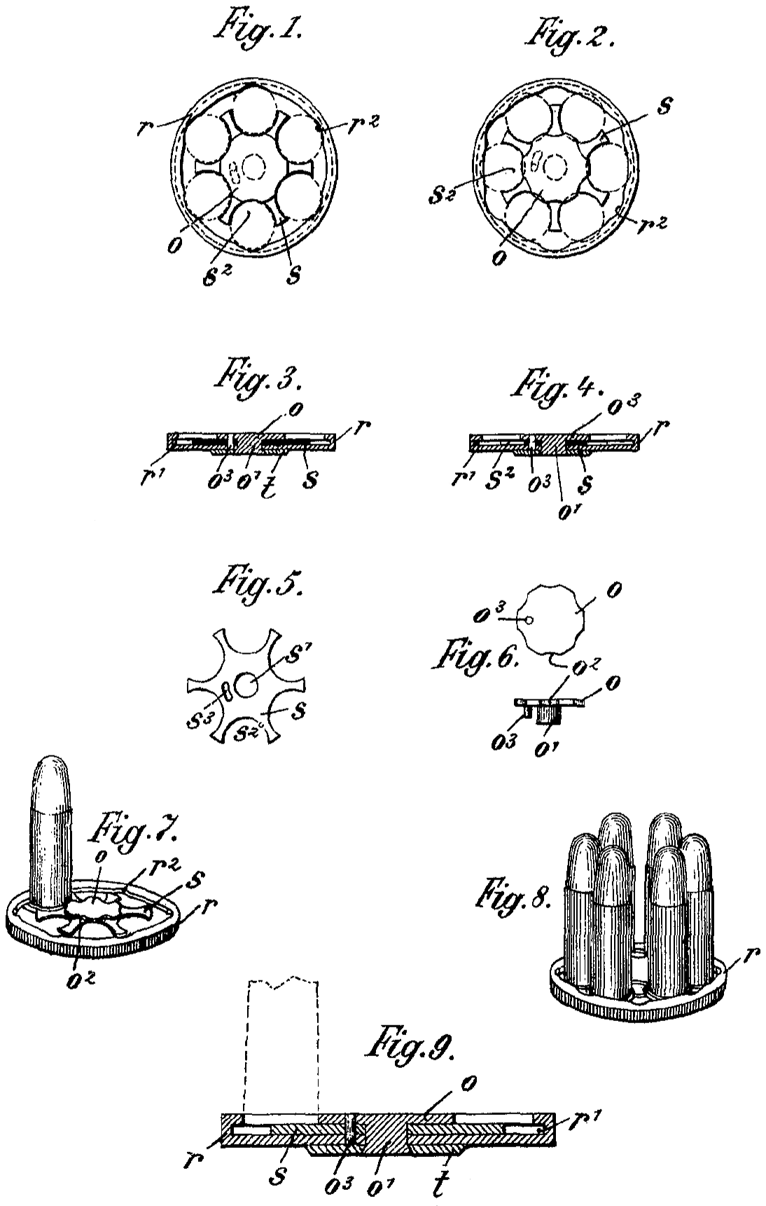
The magazine is externally in the form of a cylinder of greater diameter than length, and has a snag, a, projecting from one side, which fits into a notch between a shag, b, on the under side of the barrel and the frame C, into which the barrel is screwed. When the snag a on the charger is inserted into the said notch it is se cured there by means of a key, e, which enters grooves made in the adjacent sides of the snag on the barrel and that on the charger. By this means the charger is secured to the barrel in the position seen in Figs. 1 and 2.
The magazine is composed mainly of two parts— the body F, which has a central cylindrical chamber, N, to contain an axle and spiral spring, g², coiled around it, and a spiral chamber, H, Fig. 6, that will contain thirty cartridges, more or less, and a cap, I, to cover the chamber H and protect the cartridges from damp or ignition. The spiral chamber commences at the outer periphery of the case of the chamber H, Fig. 6, at j, and, taking about a turn and a half, terminates at H, where there is an aperture, K, for the discharge of the cartridge l² through aperture X of the frame C.
The spiral chamber His fitted with a driver or piston, n², which traverses it from end to end. The driver is carried by an arm, p², to which it is connected at its outer end, and which passes through a mortise in the outer end of a central axis, m², which turns in suit able bearings within the chamber N. As the driver n² traverses the spiral chamber H its distance from the central axis m² is continually varying, and to provide for this variation the arm p² by which it is carried slides end Wise back and forth through the mortise in the axis m², so as to make its acting radius correspond to that of any part of the groove H in which the driver n² may at the time hap pen to be.
The use of the driver is to press the cartridges continually toward that end of the chamber FI at which they are discharged, and in order that it may thus act a spiral spring, g², is coiled around the axis m², which constantly tends to turn it in the direction indicated by the arrow, and with it the arm p², which keeps the driver pressed against the cartridges l², as seen in Fig. 6, in order that as fast as a cartridge is removed from the front end, H, of the groove Hits place is sup plied by the driver n² pushing the whole row forward, so that the foremost of them will take the place of that which was last discharged, to be discharged next.
The cartridges l² are discharged one at a time by means of a piston or ramrod, r², which slides within the hollow standard S², that pro jects from the cap J of the magazine parallel to the barrel Z, and in a line with the lower most chamber of the breech, the opening within the standard S² extending through the cap J and the body F. This piston has two arms, u² u², projecting through a slot, v², in the side of the standard S², and the outer extremity of each arm is fitted with an eye which has a screw cut in it, into which the rod W is fitted, as represented in the drawings.
The rod W enters from these arms through the magazine and terminates in an eye, M, in a convenient position for the first finger of the hand to reach and pull it back, while the middle finger can reach and operate the cocking lever T. The rod W is, in this instance, arranged on the left side of the pistol, and is, therefore, adapted to a left-handed person; but the spiral chamber of the magazine can easily be made to diverge from the center in the opposite direction, and the rod W be placed on the right side of the pistol, to adapt it to a right-handed person.
A spring, U, is attached to the cap J by one end, and at the other bears against the inside of the arm u², tending continually to press the piston r² toward the outer end of the standard S². The cartridges l² are made in the usual manner and of the proper size to fit the chamber in the breech B. The width of the spiral chamber is such that the cartridge will pass freely along it, and the cartridges are packed in closely together, as represented. When a chamber of the breech is to be loaded, the operator has simply to pull the rod W by its ring M with his finger, when the piston r² will press against the outer end of a cartridge, l², in the chamber and force the same through the opening k into the lower chamber of the breech, the piston being of such a length as to force the cartridge home, and thus, in addition to its duty of transferring the cartridge from the magazine into the breech, it acts also as a ramrod. As soon as a cartridge has thus been loaded into the breech the operator with draws his finger from the eye M of the rod W, which is instantly drawn back, together with the piston r², by the spring U, and ready to transfer another cartridge into the breech upon the latter being turned so as to bring one of its empty chambers opposite the charging hole X, and to carry the loaded chamber opposite the barrel Z, to be fired by pulling the trigger T. The driver n² meanwhile under the pressure of the spring g² forces the cartridges along the chamber, so as to bring another in front of the piston r², ready to be transferred into the breech.
By this arrangement the lever T can be pulled by the middle finger of the operator alternately with the pulling of the rod W by his first finger, and thus the operation of loading and discharging will go on regularly and alternately until all the cartridges of the magazine are fired one at a time.
It is obvious that the construction of the magazine, the arrangement of its details, and the manner of attaching it to this or other fire-arms (for it is adapted to any kind of turning or reciprocating breech fire-alms) may be modified to an almost unlimited extent without any departure from the principle developed in the construction and arrangement herein particularly represented and described.
I have herein described the magazine as applied to a rotating or turning breech; but it is applicable, and I intend to apply it, to fire arms of all descriptions that are loaded at the breech. This part of my improvements, there fore, as well as several of the other parts, may, with great advantage, be applied without the rest to the improvement of different kinds of fire-arms now known.
I am aware that a machine or charger is de scribed in the patent for a shoe-pegging machine granted to John Robinson, October 31, 1848, but I make no claim to anything in it.
What I claim as my invention, and desire to secure by Letters Patent, is—
1. I claim arranging the cock in such manner that it may be raised and will stand up without being held by a sear or catch, and may then be gradually lowered again without tripping to fire the charge, or may be tripped to fire the charge, at the option of the opera tor, whether the devices employed be such as are herein particularly described or the equivalent thereof for producting the same result.
2. The movable stop s, operated upon by a stud or button protruding through to the out side of the stock, in combination with a fixed rest, b, and the jack n, substantially as described, for the purpose of preventing the jack being thrown far enough back to clear the tongue through which the trigger acts upon it, whereby the escape of the driver or hammer is rendered impossible while the stop is in operation.
3. I claim the magazine constructed with a self-acting driver, n², which places the cartridges in succession in front of the discharger, and with a discharger, r², that will draw itself back and place the pulling-rod W in the proper position for transferring the cartridges into the breech, so that they may be transferred as required by simply pressing with the finger upon the pulling-rod.
CHARLES N. TYLER.
Witnesses:
John Woods,
Zachariah Brown.