Germany 95614
PATENTSCHRIFT
— Nº 95614 —
KLASSE 72: Scuusswaarren, Geschosse, Verschanzung.
COLOMBO RICCI in LONDON.
Kniegelenkverschlufs für selbstthätige Feuerwaffen mit festliegendem Lauf.
Patentirt im Deutschen Reiche vom 29. Mai 1895 ab.
Den Gegenstand vorliegender Erfindung bildet eine selbstthätige Trommelmagazinfeuerwaffe. Der Zweck derselben besteht darin, bei Revolvern die Thätigkeit des Ladens und Herausziehens der leeren Hülse, sowie des Spannens des Schlagbolzens entweder durch den Druck der Gase auf die Vorderfläche des Kolbens oder durch einen Handdruck zu bewirken.
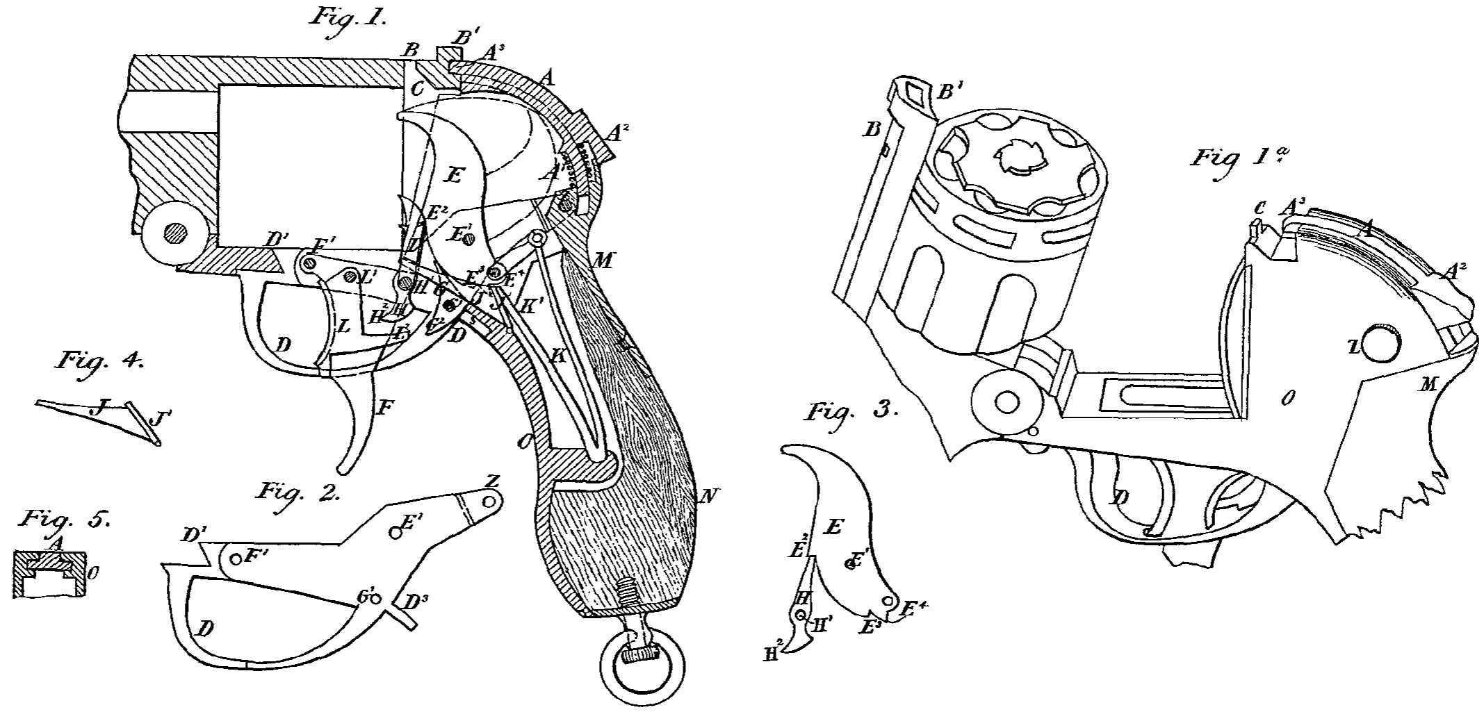
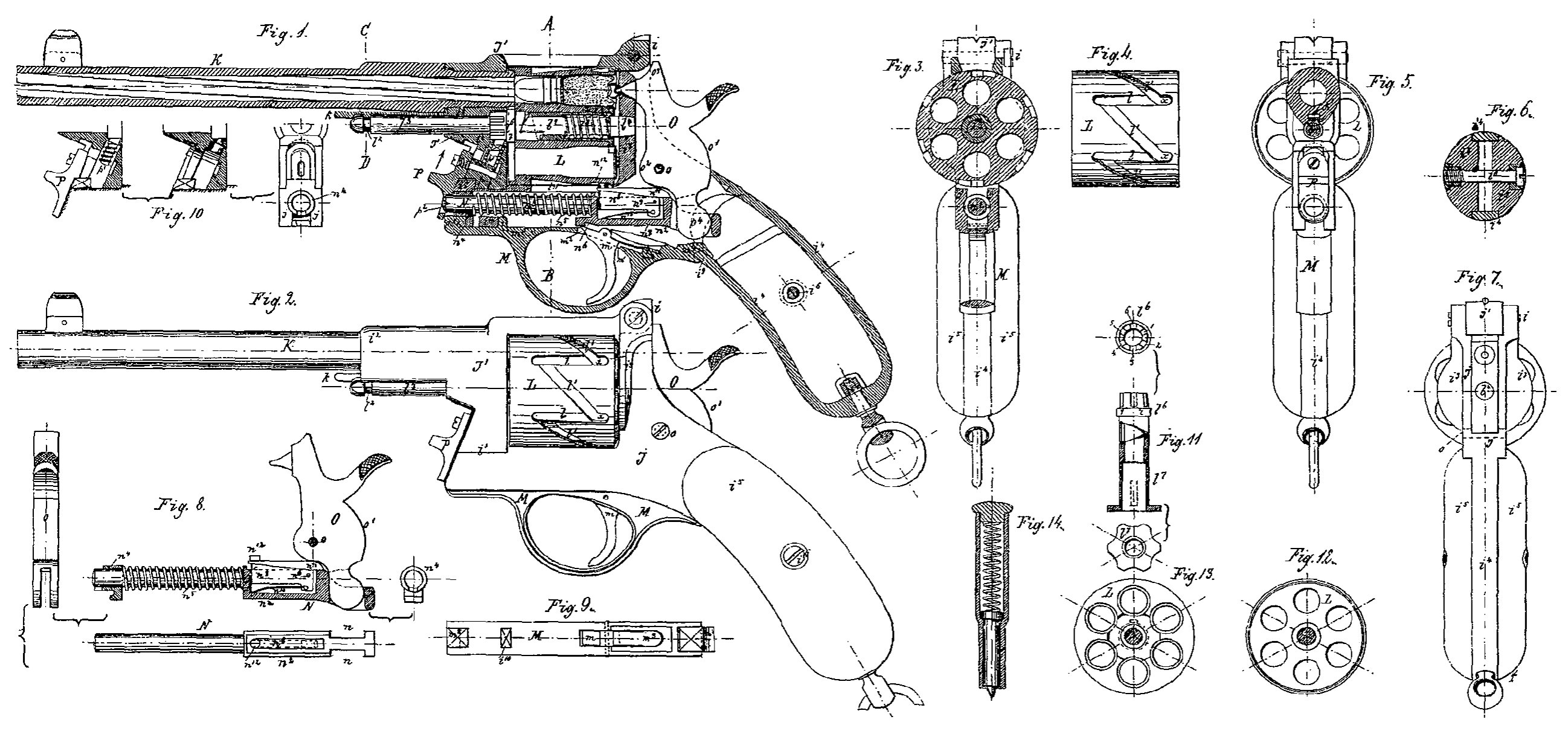
Auf der Zeichnung ist eine solche Trommelmagazinfeuerwaffe im theilweisen Schnitt dargestellt.
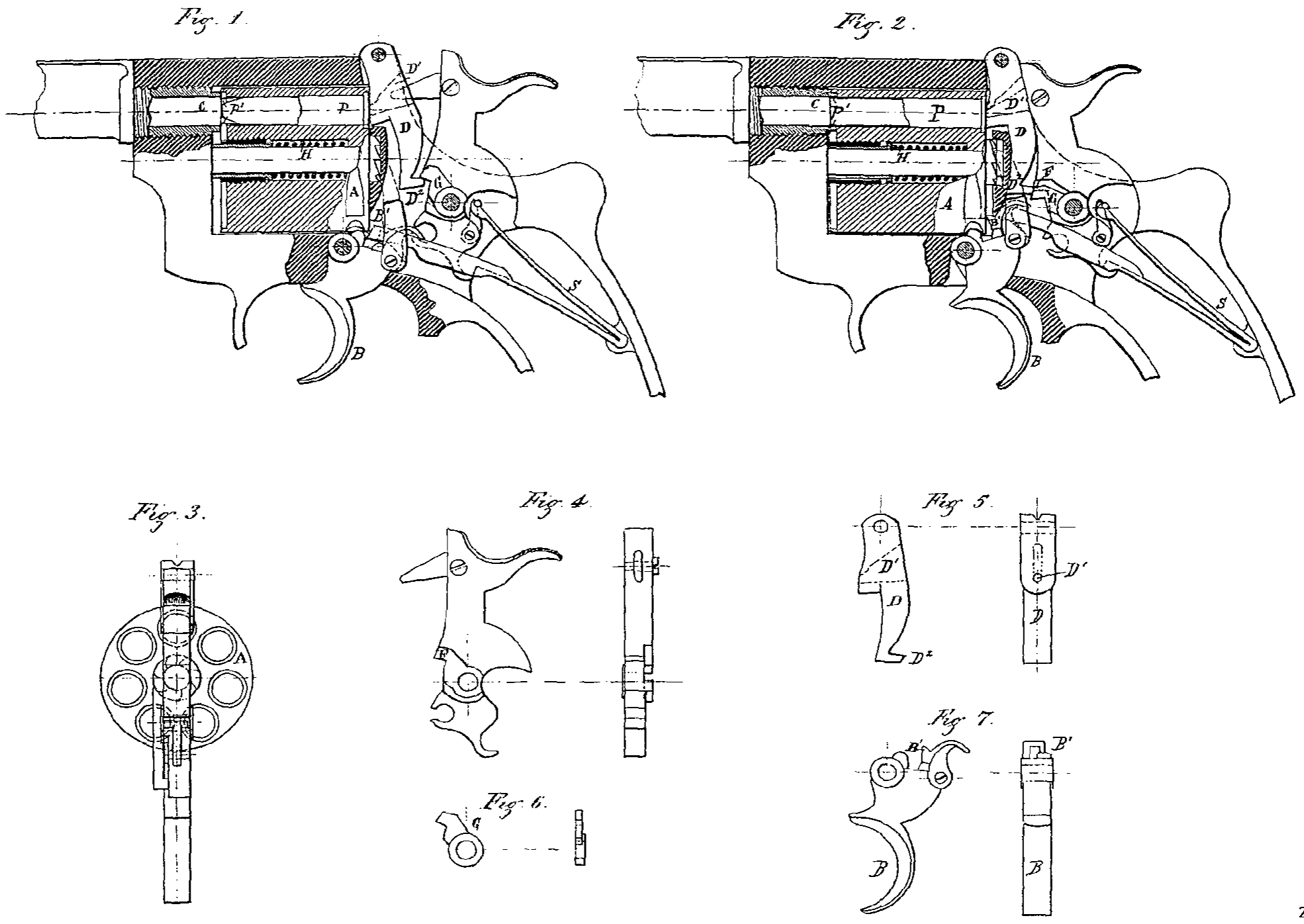
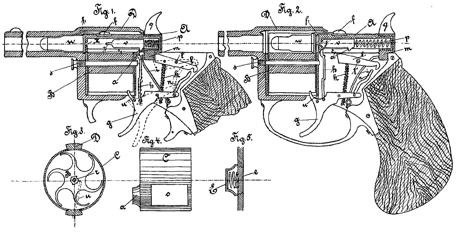
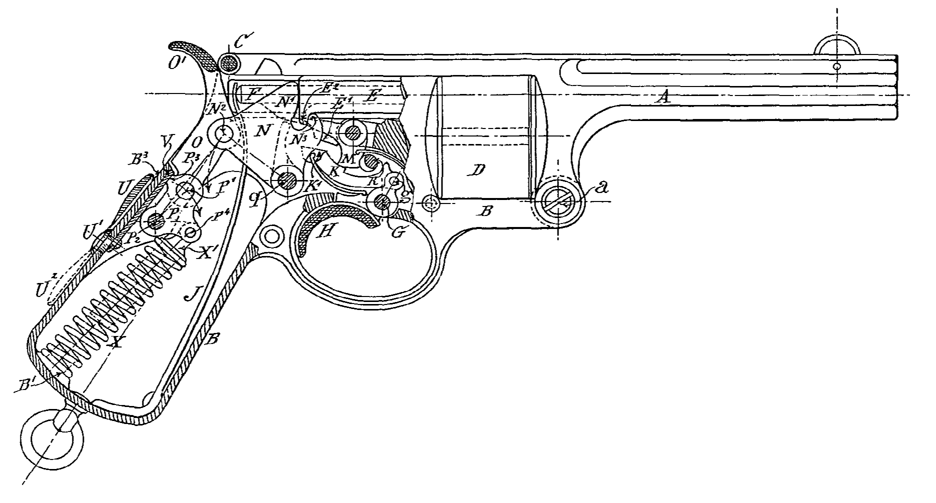
Der bei g drehbare Hebel N, welcher die Rückwärtsbewegung des Verschlufsbolzens E bei N¹ aufnimmt, ist in der Mitte ausgefräst, um der Feder J zu gestatten, frei auf den Schlagstift F zu. wirken. Der Hebel O, an dem bei N² der Hebei N gelenkig angeordnet ist, schwingt mittelst Zapfens P¹ an dem um P² drehbaren Gelenk P. Die Schraubenfeder X ist mittelst des Ansatzes X¹ am Gelenk P bei P⁴ befestigt und stützt sich am unteren Ende gegen den Griffkörper. Die Feder X wird durch Niederdrücken des Daumens O¹ gespannt.
Der Vorsprung P³ des Gelenkes P schlägt gegen den Schieber V und hemmt die Gelenke O und P, wenn die Wafle für selbstthätige Wirkung eingestellt ist. Der Schieber V kann mittelst des am Hebel-U sitzenden Excenters U¹ auf-und niederbewegt werden.
Wenn der Hebel U die punktirte Stellung einnimmt, so befindet sich der Schieber V nicht zwischen dem Ansatz P³ und dem Griflkörper B, in welchem Falle dieser Ansatz P³, anstatt den Schieber V zu berühren, gegen die innere Kolbenwandung bei B³ trifft. Der Vorsprung N³ des Hebels N dient zum Zurückziehen des Verschlufsbolzens E mittelst des Vorsprunges E².
Soll die Waffe selbstthätig arbeiten, so mufs der Hebel U aufwärts gedreht werden, so dafs das Gleitstück V zwischen B³ und dem Ansatz P³ liegt.
Die Theile sind auf der Zeichnung in der Lage dargestellt, welche sie gleich nach dem Abfeuern eines Schusses einnehmen, bevor der Finger den Drücker freiläfst.
Die Entzündung der Patrone treibt den Verschlufsbolzen E rückwärts gegen den Hebel N und den Schlagstift F gegen die Feder J. Der ganze Stofs des Verschlufsbolzens wird schliefslich durch den Stift P² und die Feder X aufgenommen.
Die Rückbewegung des Bolzens E bewirkt, dafs der Hebel N um den Stift q schwingt und die Gelenke O und P sich in der Pfeil richtung drehen und so die Feder X zusammendrücken, zugleich wird die Schlagfeder gespannt.
Sobald alle durch den Verschlufsbolzen aufgenommene Energie vollkommen verbraucht ist, wirkt die Feder X und läfst alle Theile die auf der Zeichnung dargestellte Stellung. einnehmen.
Wili man diesen Revolver durch Hand bethätigen, so mufs der Hebel U in die punktirte Stellung gedreht werden.
Diese Bewegung zieht den Schieber V unter dem Vorsprung P³ hervor, und die Gelenke O und P nehmen unter Einwirkung der FederX eine solche Stellung ein, dafs der Mittelpunkt von P¹ links von der Verbindungsstelle der Mittelpunkte von N² und P liegt, in welcher Stellung der Rückstofs durch den Zapfen P² aufgenommen wird. Beide Gelenke O und P und der Hebel N stehen hierbei fest, weil nunmehr die Mittelpunkte der Stifte P² P¹ N² in einer Geraden liegen und der Rückstofs nur auf den Stift P² wirkt.
Beim Abfeuern einer jeden Patrone hat man nur nöthig, den Daumen O¹ des Gelenkes O niederzudrücken. Diese Bewegung spannt den Schlagbolzen und zieht die leere Patronenhülse aus dem Lauf. Die entgegengesetzte Bewegung, welche durch die Feder X erzeugt wird, dreht die Trommel D und bringt eine neue Patrone vor den Verschlufsbolzen, welcher sie in den Lauf schiebt, so dafs die Waffe von neuem schufsfertig ist.
Patent-Anspruch:
Eine Ausführungsform des unter Nr. 93213 patentirten Kniegelenkverschlusses für selbstthätige Feuerwaffen mit festliegendem Lauf, gekennzeichnet durch ein innerhalb des Hand-griffs der Waffe mittelst eines Zapfens P² anelenktes Kniegelenk O P, welches einerseits durch einen schwingenden Hebel N mit dem Verschlufsbolzen E, andererseits mit einer Schraubenfeder X in Verbindung steht, und dessen Knickpunkt P¹ sich entweder unter dem Einflufs der Feder X derartig einstellt, dafs der Verschlufs ein. starrer wird, oder mittelst eines Schiebers V derartig über die Todtpunktlage hinausgebracht wird, dafs der Verschlufs sich selbstihätig zu öffnen vermag.