US 116593-RE10257
UNITED STATES PATENT OFFICE.
FREEMAN W. HOOD, OF NORWICE, CONNECTICUT,
REVOLVING FIRE-ARM.
SPECIFICATION forming part of Reissued Letters Patent No. 10,257, dated December 5, 1882. Original No. 116,593, dated July 4, 1871. Application for reissue filed October 2, 1882.

To all whom it may concern:

Be it known that I, Freeman W. Hood, of Norwich, in the county of New London, of the State of Connecticut, have invented a new and useful Improvement in Revolver Fire-Arms; and I do hereby declare the same to be described in the following specification and represented in the accompanying drawings, of which—

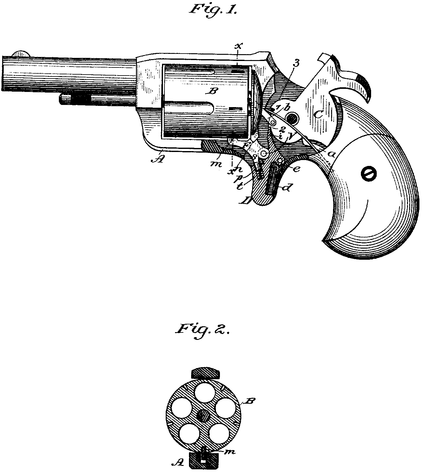
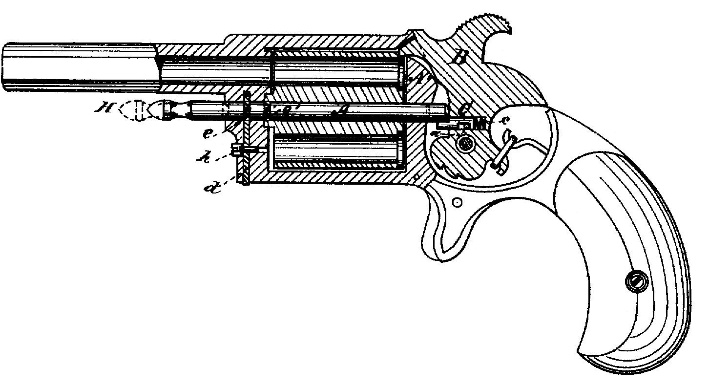
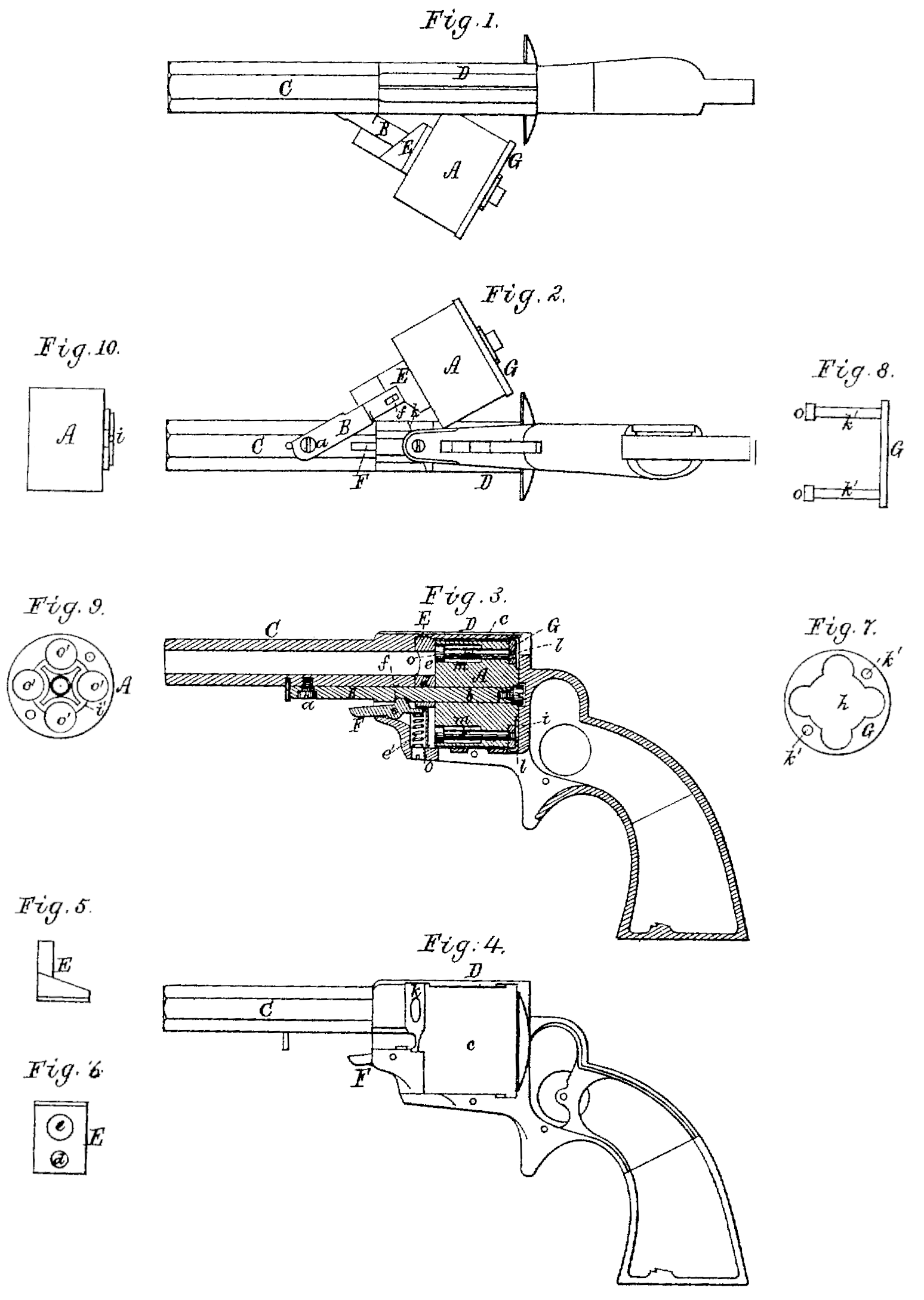
Figure 1 is a top view, and Fig. 2 a bottom view, of a pistol provided with my invention, the rotary charge-magazine being represented in such figures as drawn laterally out of the stock. Fig. 3 is a vertical and longitudinal section of the fire-arm, showing the charge magazine as within the stock, or the chamber or space thereof for reception of such magazine.

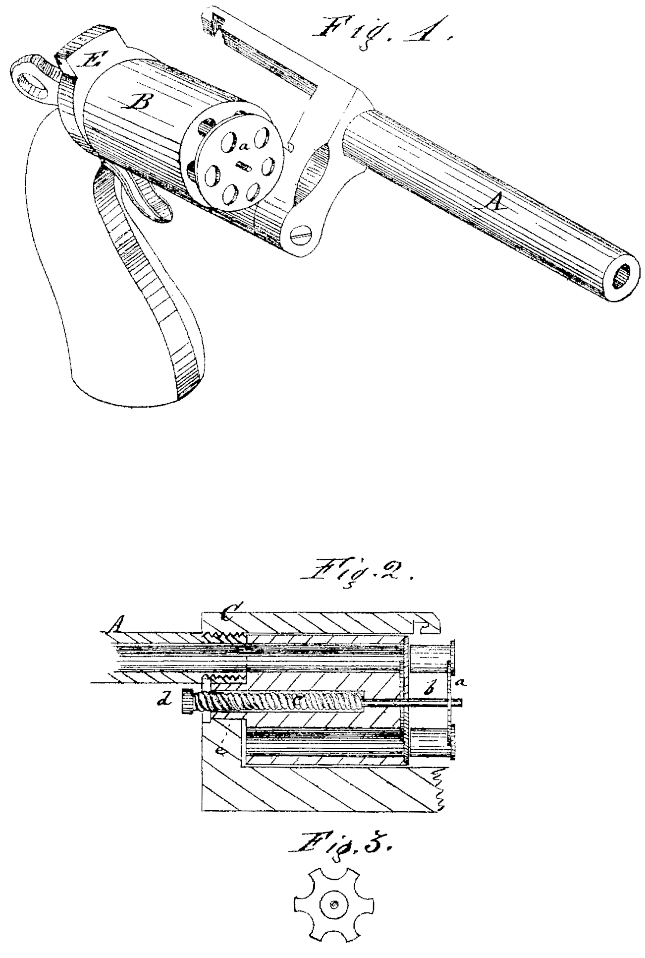
In this pistol the rotary charge block or magazine A is pivoted upon a swinging arm, B, which, at or near its front end, is jointed or pivoted to the barrel C, the joint pin or pivot being seen at a. That part of the swinging arm on which the magazine revolves is shown at b, it being of sufficient length to admit the magazine to slide the necessary distance lengthwise on it.

The recess in the stock D for the reception of the magazine is shown at c, especially in Fig. 4, which is a side view of it as it appears without the magazine and its appurtenances.

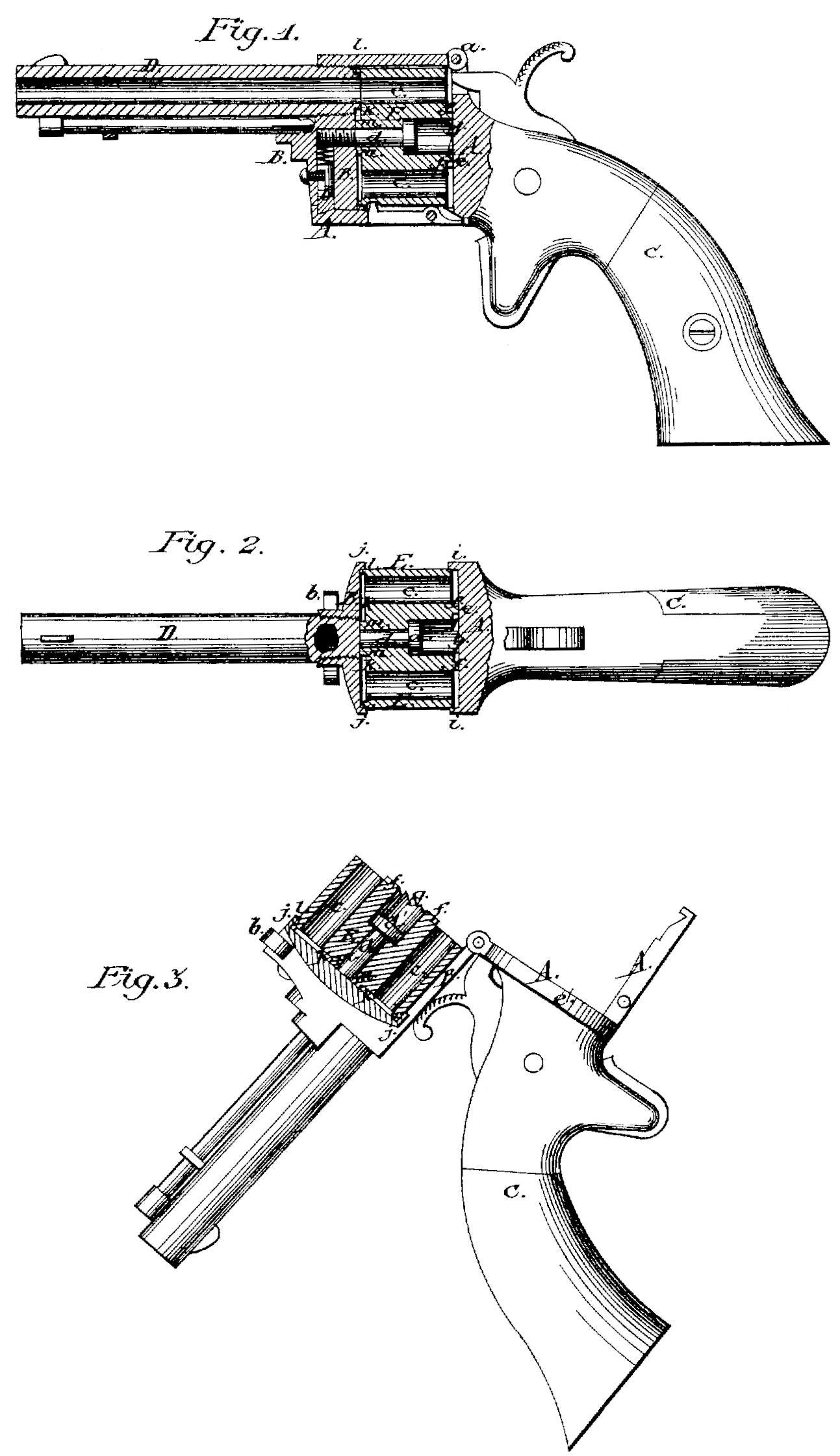
In advance of the magazine and upon the swinging arm is a slide-piece, E, formed as represented, and particularly in Fig. 5, which is a top view, and in Fig. 6, which is a rear elevation of it. It will be observed that it is a wedge-shaped block of metal, provided not only with a suitable opening, d, to receive the swinging arm, but with a bore or hole, e, corresponding in diameter with that of the barrel, and constituting a continuation of the bore of the barrel when the slide-piece is with in its socket. The rear end of the barrel, or that part of the magazine-socket next to the front face of the slide-piece, is beveled to correspond with the bevel of the front of the slide piece, and to operate as an abutment for the slide-piece, and to constitute a cam, k, to press it back while the magazine is in the act of being moved into its recess.

A lever-latch, F, provided with an actuating spring, e’, pivoted in the stock and arranged as shown, serves, by catching into a recess or notch, f, in the swinging arm, when the latter is in its innermost position, to hold the arm and the magazine in place relatively to the stock, or while the piece may be fired.

The slide-piece E is to admit of the magazine being moved laterally out of its recess and into it, as occasion may require. The slide-piece enables the magazine to slide forward on its spindle while both are being moved out of the recess, the movement being sufficient to prevent the back of the recess from stopping the magazine. While the magazine is in the act of being moved inward the slide piece, by the action of the beveled cam, will, with the magazine, be forced back on the spindle or pivot of the magazine, and when the magazine may be back in the recess such slide-piece will hold it in its rearmost position therein.

Against the rear end of the magazine is the cartridge-retractor G, it being formed as shown in rear view in Fig. 7 and in side view in Fig. 8. Fig. 9 is a rear end view, and Fig. 10 a side view, of the magazine without the retractor. The said retractor G is a disk or circular plate, perforated, as shown at h, to fit upon the rear part or projection, i, of the magazine. The retractor has a diameter a little greater than that of the magazine, and is connected to such magazine by two projecting pins, k’ k’, that enter corresponding holes in the magazine and slide freely therein. The pins k’ k’ are kept in connection with the magazine and retractor by means of screws l l, screwed into said retractor, and heads o o on the other ends of the pins, said heads being larger in diameter than and projecting beyond the body of the pins, and arranged in stop sockets or bores m m, as shown. By talking hold of the retractor with the thumb and index-finger, applied to opposite parts of its periphery, the retractor, when the magazine is out of its recess, may be drawn backward, so as to extract at once from the magazine. all the cartridges or cartridge-shells that at the time may be in the charge chambers o’ o’ o’ o’ thereof.

I do not claim a cartridge-extractor as made and applied to a magazine in manner as shown in the United States Patent No. 45,912; nor do I claim anything described and shown in the United States Patent No. 26,919.

I claim—

1. The stock D, having its rotary-magazine receiving chamber closed at bottom and open laterally to receive the magazine, in combination with the arm B, for supporting such magazine, pivoted to the stock or barrel so as to swing laterally or horizontally relatively thereof.

2. The magazine provided with the series of charge-chambers and with the retractor guide screw shouldered holes, as described, arranged between such chambers, and also with a cylindrical passage made through it (the said magazine) axially for reception of the swinging arm B, in combination with the stock D, having its rotary-magazine-receiving chamber closed at bottom and open laterally to receive the magazine, and with the said arm pivoted to the barrel so as to swing laterally under it, and with the retractor consisting of the perforated plate G and the headed screws k’, all being arranged and to operate substantially as set forth.

3. The wedged slide-piece E, arranged in advance of the rotary magazine, and adapted with it to slide on the pivoted arm B lengthwise thereof, in combination with the said arm and magazine, and with the stock provided with the abutment or cam k arranged in it (the said stock,) and for operating the said slide piece E, all being substantially as set forth.

FREEMAN W. HOOD.

Witnesses:
R. H. Eddy,
E. B. Pratt.


US 210725-RE9704
UNITED STATES PATENT OFFICE.
ALONZO L. SWEET, OF NORWICH, CONNECTICUT, ASSIGNOR TO THE BACON ARMS COMPANY, OF SAME PLACE.
REVOLVING FIRE-ARMS.
SPECIFICATION forming part of Reissued Letters Patent No. 9,704, dated May 10, 1881. Original No. 210,725, dated December 10, 1878. Application for reissue filed April 11, 1881.

To all whom it may concern:

Be it known that I, Alonzo L. Sweet, of Norwich, in the county of New London and State of Connecticut, have invented certain new and useful Improvements in Revolving Fire-Arms; and I do hereby declare that the following is a full, clear, and exact description of the invention, which will enable others skilled in the art to which it appertains to make and use the sane, reference being had to the accompanying drawings, and to the letters of reference marked thereon, which form a part of this specification.

My invention relates to revolving fire-arms; and it consists of an improved stop mechanism of simple and inexpensive construction, whereby the cylinder is locked in proper position for discharging or in discharged position, at all times, excepting when at half-cock. Numerous devices have been described or used, and are well known for this general purpose of securely locking and unlocking the cylinder at the proper times, and no particular description of them is deemed necessary.

The main object of this invention is to secure the same certainty of operation as that heretofore attained, by fewer parts and a simple and cheaper structure.

I have hereinafter particularly described my improvements in connection with other and old parts, and have specifically pointed out my invention in the claims.

The annexed drawings, to which reference is made, represent, in Figure 1, a section of the working parts of a revolver embodying my invention. Fig. 2 is a transverse section on line x x of Fig. 1.

A represents the frame of a revolver with recoil-shield. B is the cylinder. C is the hammer, having the two notches 12 for half-cock and full-cock. a. is the hammer-spring. b is the arm or pawl pivoted on the hammer and passing through a slot in the recoil-shield to engage with the ratchet on the end of the cylinder for rotating the same.

The trigger is shown at D, and is pivoted on its rear upper projection, e, the ordinary spring d, for throwing it forward, being located in a recess below the pivot.

The stop is represented at F. It lies in a groove, f, in the lower strap of the frame, which groove extends rearward under the lower edge of the recoil-shield n. When placed in this groove the forward end of the stop F may be pressed up, so that said forward end in may rise above the interior surface of the strap and project into the notch in the cylinder, by which said cylinder is locked. The rear end of the stop F extends back to the trigger D, to which it is connected at a point, v. The upper edge, of the stop F bears against the lower edge of the recoil-shield, as shown at n.

It will be observed that the point of connection v between stop F and trigger D is in such relation to the pivotal point e of the trigger and the bearing or fulcrum n of the stop that motion of the pivotal end of F up will fulcrum the stop over the edge of the recoil-shield and depress the front end of the stop. For the effectual working of this stop it is necessary that it should be pressed upward in order to interlock with the notches of the cylinder. This is effected by means of a spring, t, in a hole in the trigger, which spring presses a pin, p, upward against a projection, s, on the lower edge of the stop.

An Ordinary point, i, on the upper end of the trigger bears against the cam-face of the hammer. When this rests upon the high part 3 of said cam-face the point v is depressed, the front end of F raised, and the cylinder locked. Upon raising the hammer the point i falls in to the half-cock notch 1, letting the spring d throw forward the trigger, and thus throw up the rear end of the stop F and unlock the cylinder. The cam-face is low from this half cock notch a sufficient distance to allow the cylinder to turn its notch out of register with the stop, and then rises as high as the high part 3, so as to press forward (see Fig. 1) the spur i, thereby depressing the stop and giving it spring-tension enough to force the stop into the next notch in the cylinder as soon as it comes into line.

As in the act of firing the trigger is drawn back, it is evident that the connected rear end of the stop will then be depressed and the front end locked into the cylinder, and that the cylinder is unlocked only at the moment when in | cocking the point i falls into the notch 1, and thereafter in the ordinary motion till the stop falls into the next notch. No adjustment of the parts is needed, except to fit the stop in the slot, and then to see that the forward end does not rise too far when the piece is at half-cock, it being necessary that the cylinder should ride freely over the stop when said stop is down.

Having thus described my invention, what I claim as new, and desire to Secure, is—

1. In a revolving fire-arm, the stop F, located in a groove in the lower strap and fulcrumed on the lower edge of the recoil-shield, in combination with a spring underneath said stop and with the trigger, substantially as described.

2. The trigger D, pivoted at e, in combination with a stop, F, located in a groove in the lower strap, having its fulcrum on the lower edge of the recoil-shield, and having also a spring underneath it, said trigger operating said stop at the point v, substantially as described.

3. The combination of the trigger D, pivoted at e, and having the point i, with the stop F, connected thereto at , said stop being fulcrumed on the edge of the recoil-shield, and being also forced upward by a spring, substantially as described.

4. In a revolving fire-arm, the combination of the trigger, the stop jointed to the trigger, a fulcrum on and below the recoil-shield for the stop, and a spring in the trigger for adjusting the stop, all substantially as and for the purposes set forth.

In testimony whereof I have hereunto set my hand.

ALONZO. T. SWEET.

In presence of—
Norris G. Lippitt,
Stephen B. Meech.


US 165098-RE6715
UNITED STATES PATENT OFFICE.
CHARLES. W. HOPKINS, OF NORWICH, CONNECTICUT, ASSIGNOR OF ONE HALF INTEREST TO MERWIN, HULBERT & CO.
IMPROVEMENT IN SAFETY-CATCHES FOR REVOLVERS.
Specification forming part of Letters Patent No. 165,098, dated June 29, 1875; reissue No. 6,715, dated October 26, 1875; application filed September 14, 1875.

To all whom it may concern:

Be it known that I, Charles W. Hopkins, of Norwich, Connecticut, have invented an Improvement in Fire-Arms, of which the following is a specification, reference being had to the drawing hereto annexed forming part of the same.

My invention consists in a locking device relating to the locking of the hammer of a revolver fire-arm, so that when the device is employed or used the hammer cannot be cocked for firing without first being released from the locking device; and consists of a projection on the lower anterior part of the hammer, so arranged that the axial pin on which the cylinder revolves may be pushed back through the recoil-shield, and made to engage with said projection in the hammer, and thereby, when the hammer is let down onto the rear of the cylinder, lock it in such position.

Figure 1 is a side view of a revolver-pistol containing my devices.

It is deemed unnecessary here to describe the general mechanism, which is common, confining myself chiefly to the description of the particular devices which I claim as new.

A is the axial-pin of the cylinder, extending through the recoil-shield A’. B is the hammer; C, a pin, which I call “locking-pin,” placed in a recess in the lower anterior part of the hammer. A pin, a, passing through a broad notch in the locking-pin C, holds the latter in place, while it is permitted to move back against a small spiral spring, c, at the bottom of the recess, which keeps the said locking-pin C pressed outward. The parts are so arranged that when the hammer is thrown down upon the rear of the cylinder, and the axial pin is forced back, it will come in contact with the anterior edge of the hammer-shaft immediately above the locking-pin, thereby, as is evident, preventing the hammer from being raised and cocked without first pulling forward the axial pin out of engagement with the locking-pin. To hold and detain the axial pin in the two positions indicated, it is provided with two annular notches or recesses, e e’, and there is provided a stop-lever, d, pivoted in the frame at h, a spring underneath it acting to press the upper end into engagement with the said annular notches, the lower end projecting outside of the frame, exposed to the pressure of the finger. When the axial pin is pushed back into engagement with the locking-pin on the hammer the said stop-lever will engage with the notch, e, and when it is pulled out of such engagement it will rest in the notch e’. To lock the hammer so that it cannot be cocked for firing, press down the stop-lever d, push the axial pin through the aperture in the recoil-shield, where the said axial pin will engage with the locking-pin, thus preventing the hammer from being raised, and the stop-lever d, dropping into and engaging with the annular recess e on the axial pin, will prevent said pin from moving forward. By raising the stop-lever and pulling the axial pin forward the hammer is unlocked. A spring-face may be secured on the rear end of the axial pin, and the locking-pin on the hammer-shaft be made fixed. It is necessary that either the locking-pin or the face of the rear end of the axial pin be movable, in order that if the axial pin be pushed back when the hammer is raised, when the hammer is thrown down in the act of firing the arm it will not be prevented from doing so, but that the locking-pin will pass over the rear end of the axial pin.

I claim—

1. In a revolver fire-arm, a locking device connected with the hammer, whereby, in combination with the axial pin of the cylinder, the hammer may be locked and unlocked, as described.

2. The combination of the axial pin A, provided with the annular notches e e’, the stop-lever d, and the locking-pin C, on the hammer B, as and for the purpose described.

Witness my hand this 8th day of September, 1875.

CHAS. W. HOPKINS

Witnesses:
Lewis A. Hyde,
E. W. Tibbits.


US 157860-RE7610
UNITED STATES PATENT OFFICE.
DANIEL MOORE, OF BROOKLYN, NEW YORK, ASSIGNOR TO MERWIN, HULBERT & CO, OF NEW YORK CITY.
IMPROVEMENT IN REVOLVING FIRE-ARMS.

Specification forming part of Letters Patent No. 157,860, dated December 15, 1874; reissue No. 7,610, dated April 17, 1877; application filed March 30, 1877.

To all whom it may concern:

Be it known that I, Daniel Moore, of Brooklyn, in the county of Kings and State of New York, have invented certain new and useful Improvements in Revolving Fire-Arms; and it is hereby declared that the following is a full, clear, and exact description thereof, that will enable others skilled in the art to which it appertains to make and use the same, reference being had to the accompanying drawings, and to the letters of reference marked thereon, which form a part of this specification.

This invention relates to revolving fire-arms designed to use metallic-cased cartridges; and it consists in the construction and combination of parts, as will be hereinafter more fully set forth, and pointed out by the claims.

In the annexed drawings, Figure 1 is a vertical central section of a pistol embodying the invention. Fig. 2 is a rear-end view of the same. Fig. 3 is a cross-section on the line y y, Fig. 1. Fig. 4 is a face view of the spring stop, by which the barrel, in sliding on the center-pin, is stopped at a given point. Figs. 5 and 6 are opposite face views of a key employed in locking the barrel on the center-pin. Fig. 7 is a side face view of the center-pin attached to the stock on which the cylinder revolves, and by which the barrel is connected with the stock. Fig. 8 is a top face view of the same with the cartridge-extractor and its sleeve in section. Fig. 9 is a rear face view of the cartridge-extractor, with the end of the cylinder shown by dotted lines. Fig. 10 is a cross-section of the pistol on the line x x, Fig. 1. Fig. 11 is an upper face view of the end of the stock of the frame. Fig. 12 is a side view of a section of the barrel and bracket, slowing an opening for the locking key-bolt. Fig. 13 is a side view of a broken piece of the rear end of the barrel and bracket, and the front end of the cylinder. Fig. 14 is a rear. end view of the barrel and bracket.

A is the barrel; ; B, the cylinder, and C the frame.

The mechanism of this pistol, (shown in the drawing,) so far as relates to the hammer, trigger, main and sear springs, and the de vice for locking the cylinder rotarily, does not differ essentially from that now in use; a particular description of the same is therefore unnecessary.

D is the cartridge-extractor. It consists of a circular plate of metal, which fits into a corresponding circular recess in the rear end of the cylinder B. The peripheral line of this circular plate preferably coincides with a circle drawn through the centers of the several chambers of the cylinder, and semicircular notches a are made in the periphery of the said plate, corresponding to the said several chambers, so that when the said plate is in place in the circular recess in the cylinder, and cartridges are inserted in the chambers, a part of the circumference of the cartridges at their bases will lie within said semicircular notches, aid corresponding portions of their projecting heads rest against the outer face of such plate, whereby, when the cylinder is drawn away from the said plate, the latter will act to withdraw the cartridges or their cases from the cylinder. This extractor is attached to a sleeve, E, which fits loosely on to the center-pin F, and enters the cylinder but only a portion of its length, the cylinder through which passes the center-pin being bored out to receive the sleeve, forming an annular recess between the center. pin and the cylinder the length of the sleeve, or a little longer, and the length of the sleeve is somewhat greater than that of the cartridge, so that when the cartridges are drawn by it entirely from the cylinder, the forward end of the sleeve will still remain in the cylinder.

A feather, c, on the sleeve passes into a slot in the cylinder, thereby securing the rotation of the cylinder with the extractor, and securing the adjustment of the notches to the chambers of the cylinder. On the rear face of the said extractor is the ratchet-wheel or annulus d, which is actuated by the pawl-lever e, (dotted lines,) to revolve the retractor, and with it the cylinder. In the center-pin F is fixed a stop pin, f, between which and the end of the sleeve E there is some space, h. This permits a longitudinal movement of the sleeve on the pin, thereby preventing the cartridge-shells, after being withdrawn from the cylinder by sliding the cylinder forward on the center-pin, from being retained by their heads binding between the extractor and the recoil-shield g.

G is a bracket, made in one piece, solid with the barrel. It is bored nearly through longitudinally to receive the cylindrical center-pin F. I is a slot or opening through the bracket, to receive the locking key-bolt J. L is a retaining-stop, pivoted in an opening in the side of the bracket, and pressed into engagement With the notch or slot k in the center-pin by a spring, i. The said transverse slot k opens into a longitudinal slot, k’, thus permitting the brackets and barrel to be drawn off from the center-pin, until the nose of the catch L, in traversing the said slot k’, is stopped against the end of said slot. Then, if it is desired to remove the barrel entirely from the center-pin, it may be done by pressing upon the lower end of the catch L, thereby lifting its nose out of the slot.

On the end of the center-pin F are formed key-bits o o’, the portion forming the bolts being flattened by the cutting away of about one half of its diameter, so that it may pass un der the key-bolt-J, and then, by being turned a quarter around, locked into the bolt J. Near the fore end of the strap M of the frame is a slot, m, across the same, to receive a lip or projection, n’, formed on the face of the base of the bracket G. On one side of this face is also a notch, p, to receive the lip q, to prevent the bracket G from swinging beyond its proper point. In a longitudinal groove in the upper face of the said strap is a sliding catch, r, the beveled end of which is pressed forward into the slot in by a spiral spring, s.

When the bracket is swung to its place over the strap, the lip in presses back the catch against the springs, until the bracket reaches its position, and the lip q stops in the notch p, when the said catch, under the stress of said spring, slides forward into a notch, t, cut across the lip, t, and thereby the bracket is securely looked in position. t is a finger piece, the stem of which is screwed into the said catch, through a slot in the strap, where by the said catch may be withdrawn, and the bracket unlocked from the strap.

On the forward face of the cylinder is a projecting boss, u, having an annular recess, v, next to the face of the cylinder, and upon the rear end of the barrel is formed a semi circular collar, u’, recessed to receive the projecting rim of the boss u. and cylinder are in position on the center-pin, this boss and collar form a lock, by which the cylinder is drawn forward on the pin with the barrel, and also a good gas-check. Provision is made for loading the cylinder through an opening, v, in the recoil-shield, covered by a slide, w^2, in the usual way.

By the extension of the center-pin along under the barrel within the drilled-out solid portion beneath it, which also forms the bracket-foot, when the parts are brought in position for firing, and the bracket-foot swung within the slot cut in the lower strap of the frame, all the parts are firmly locked together, and require no additional aid of key-bits, bolts, or catch devices, (to resist the recoil of the discharge,) either upon the center-pin or to act thereupon. It is evident that when the barrel with its bracket and the cylinder attached are placed upon the extended center pin, and the foot of the bracket in position, said parts cannot be separated unless by transversely breaking the center-pin, or turning the bracket-foot out away from the slotted strap, or breaking the strap, which cannot be done by any usual revolver cartridge-charge, as the lines of resistance to separate the parts are in the angles of an arch. This strong and simple construction, whereby the center-pin not only forms the base-pin for sliding forward the barrel and the cylinder, but also forms the axial pin on which the barrel is rotated upon its center, so as to allow the foot of its bracket to swing into or pass out of the slot cut in the frame-strap, constitutes an important part of the invention.

Much difficulty has been experienced in preventing the gases from the discharge passing into the assembled parts lying in front of the cylinder, and particularly so as to the center-pin, when said center-pin is extended so as to be used as a base-pin for sliding forward the barrel and cylinder, as well as for a central axial pin for rotating the same. To prevent this difficulty the barrel is constructed at its rear end with the roof-like cover u’, that extends partially down upon the bracket rear, and sufficiently surrounds the center-pin at that point to deflect and throw off the gases from the parts described, and at the same time admit the rim of the covering-boss, u on the front of the cylinder to take in the semicircular recess formed in the under part of the said deflector; thus it acts as a clutch for carrying forward the cylinder with the barrel, for extracting the cartridge-shells.

After firing this arm, the empty shells are removed as follows: The catch r is withdraw in from the notch t’ by sliding back the finger-piece t, thereby unlocking the bracket G from the strap M. The bracket and barrel are then revolved a quarter round upon the center-pin, and slid forward upon it, carrying the cylinder with them until stopped by the spring-catch L, the nose of which will have reached the end of the slot k’. The extractor, by this movement, has been carried along with the cylinder until the sleeve E reaches the pin f, when it will stop, and, there holding the empty shells, cause them to be withdrawn from the cylinder, and the extractor being carried a little distance away from the recoil-shield, fits obviating the binding of tile flanged lead of the shells between the same, the shells will readily fall out. By reversing these motions the barrel and cylinder are carried back to their first position, and there locked in place.

If it is desired to remove the barrel and cylinder entirely from the center-pin, it may be done by pressing upon the spring-catch L, thus lifting its nose out of the slot k’.

When the parts are in position, as represented in Fig. 1, the bracket is locked onto the center-pin, not merely by the catch L, which, being a spring-catch, might not be secure, but also by the key-bolt J, the key bits o o’ being then turned into the wards of the said bolt.

The use of the bolt, J separate from the barrel is recommended; but, if preferred, one or more projections may be formed on the under side of the barrel, corresponding in form and position to the body of the bolt when in place, the nose of the front end of the bracket being cut away for the purpose, and the space thereby exposed capped by a separate piece screwed on.

I am aware that revolving fire-arms with extended slide-rods and sectional cored cylinders have been used, and I do not claim such as any invention; but,

Having thus fully described the invention, what is claimed as new, and desired to be secured by Letters Patent, is—

1. In a revolving fire-arm, the combination of a barrel, a cylinder, a forwardly-projecting combined slide-rod and center-pin, and an extractor, substantially as shown, whereby a partial rotation of the barrel on said center pin permits the sliding forward longitudinally of the barrel and cylinder on said combined slide-rod and center-pill, and extracts the cartridge-shells, as specified.

2. In a revolving fire-arm, a longitudinally sliding barrel, a cylinder, and a frame-strap, constructed substantially as described, in combination with an extended slide-rod center-pin, as and for the purpose specified.

3. The combination, in a revolving fire-arm, of the center-pin F, provided with the trans verse and longitudinal slots k and k’, the spring-catch L, and the bracket G, as and for the purpose specified.

4. The combination, in a revolving fire-arm, of the center-pin F, the stop-pin f, the sleeve E, extractor D, all d cylinder B, in which the extractor is permitted to move a little distance forward on the center-pin, away from the recoil-shields, in the act of withdrawing the cartridge-shells, as and for the purpose specified.

5. The combination, in a revolving fire-arm, of the bracket G and the barrel A with the center-pin F, provided with the flattened key bits o o’ and the key-bolt J, as and for the purpose specified.

In testimony that I claim the foregoing I have hereunto set my hand this 29th day of March, 1877.

DANL. MOORE.

Witnesses:
Levi Baxter,
Edwin Moore.


US 150120-RE6569
UNITED STATES PATENT OFFICE.
BENJAMIN H. WILLIAMS, OF NEW YORK, N.Y.
IMPROVEMENT IN REVOLVING FIRE-ARMS.

Specification forming part of Letters Patent No. 150.120, dated April 21, 1874; reissue No 6,569, dated August 3, 1875; application filed July 3, 1875.

To all whom it may concern:

the city and county of New York, in the State of New York, have invented an In proved Cartridge-Extractor for Revolving Fire-Arms; and I do hereby declare that the following is a full and exact description there of, reference being had to the accompanying drawings and to the letters of reference marked thereon.

My invention relates to the cartridge-extractor of a many-chambered revolver fire arm; and consists in a true circular disk, ring, or projection concentric with the axis of the revolving cylinder, connected to the recoil shield or frame of the arm concentric to the axis of the revolving cylinder, constructed and arranged to engage, at any and all points of its periphery, with the flanged head of the cartridge-case in the cylinder, and withdraw them from their chamber in the cylinder when the cylinder is moved away from the recoil shield, this form and action obviating the necessity of rotating adjustment between the cylinder and the extractor.

To enable those skilled in the art to make and-use my invention, I will proceed to more fully describe the construction and operation of my improved cartridge-extractor, referring by letters to the accompanying drawings, in which—

Figure 1 is a partial side view or elevation of a repeating-pistol embracing my invention. Fig. 2 is a longitudinal central section of the same, and Fig. 3 is a back view of the cylinder detached.

At Fig. 1 I have illustrated the parts as they would appear while the cylinder was being drawn off of the base-pin, and the cartridge-shells being extracted.

In the several figures the same part will be found designated by the same letter of reference.

A is the many-chambered revolving cylinder; B, the base-pin or spindle on which the cylinder rotates, and C the recoil-shield or rear portion of the frame D of the pistol. This portion C is formed or provided, at e, with a projecting collar or short tube, in the outer circumference or periphery of which is turned out an annular groove or channel, as shown, close to the forward face of the shield plate C, and so as to form a shoulder, past which project (toward the base-pin B, as illustrated) the flanges of the cartridge cases or shells f. The shoulder named forms, in substance, a ring surrounding the projecting or, all parts of the periphery of which are equally distant from the axial line of the revolving cylinder A, and therefore all points, indifferently, of such periphery will engage with the flanged heads of the shells in said cylinder, thus obviating the necessity of any adjustment of the cylinder to the extractor. In the rear end of the cylinder A is cut or turned out an annular recess or groove, b, (see Fig. 3,) which, it will be observed, is concentric with the central hole of said cylinder, and with its series of cartridge-chambers, and into this recess b fits the extractor e of the recoil shield piece C, in the manner clearly shown at Fig. 2.

From this construction and combination of parts it follows that when the cylinder A is in place, and its chambers filled or loaded with cartridges f, the flanges of the latter will, at a point nearest the base-pin or center of rotation of said cylinder, project inwardly past or in rear of the extractor e of the plate C, and into the channel or groove formed in extractor e. This groove being a very little wider than the flanges of the cartridges f are thick, the part of said flanges which projects into said channel can move round freely therein with out hinderance or friction whenever the cylinder A is rotated on the base-pin B; but when ever the cylinder is pulled off of the base-pin or moved longitudinally thereon, as illustrated at Fig. 1, the said projecting portions of the flanges of the cartridges will hang in said channel or catch, and hold on against the shoulder or rear edge of the extractor e, and be detained rearward while the cylinder is being moved forward, and thus the cartridge-shells f will be effectually extracted or withdrawn from the chambers of the cylinder A whenever the latter is moved longitudinally forward on the base-pin B.

It will be seen that as the extractor e corresponds in external size and shape to the groove b, and takes bearings upon both the larger and smaller circumferences of said grooves, the Walls of the chambers of the cylinder are not practically weakened by the presence of the said groove b, said groove being always blocked up with the extractor e at the time when the chambers are being discharged of their con tents. It will also be seen that, since the ex tractor e, by which the extraction of the empty shells is effected whenever the cylinder is moved forward on the base-pin, is larger in external diameter than the circle in which lie the inner most points of the series of cartridge-flanges, its efficiency as an extractor is infallible, be cause none of the flanges of the cartridges can possibly ride over or fail to be caught upon the shoulder or catching portion of said collar.

It is of course immaterial what size or diameter be adopted for said collar and groove, and whether the collar e be made, as shown, With a channel in its periphery to accommodate the portions of the flanges nearest to the base-pin, or be made to surround the flanges of the cartridges, and with a channel in its internal surface to accommodate those portions of the flanges most distant from the axis of motion of the cylinder.

I have represented the extractor as being formed on or out of the stock of the plate C; but this detail of construction or manufacture may, of course, be varied like others, and, if deemed expedient, said collar may be made of a separate piece and secured in place either to or on said plate C or the base-pin of the pistol.

Having so fully described my invention that any one skilled can make and use it, what I claim as new, and desire to secure by Letters Patent, is—

A revolver fire-arm with a many-chambered breech-loading cylinder provided with a cartridge-extractor connected to the recoil-shield or frame of the arm, and consisting of a disk or ring, the periphery of which, that engages the heads of the cartridge-shells in the cylinder to withdraw them therefrom, is a true circle, concentric to the axis of the cylinder, all con structed and arranged to operate as and for the purpose described.

In testimony whereof I have hereunto set iny hand this 1st day of July, 1875.

BENJAMIN H. WILLIAMS.

In presence of—

B. S. Clark,
Henry Eichling.


US 29126-RE5813
UNITED STATES PATENT OFFICE.
ABRAM. J. GIBSON, OF SHREWSBURY, ASSIGNOR, BY MESNE ASSIGNMENTS, TO DANIEL B. WESSON, OF SPRING FIELD, MASSACHUSETTS
IMPROVEMENT IN REVOLVING FIRE-ARMS.
Specification forming part of Letters Patent No. 29,126, dated July 10, 1860; reissue No. 5,813, dated March 31, 1874; application filed March 25, 1874.

To all whom it may concern:

Be it known that I, A. J. Gibson, formerly of Worcester, in the county of Worcester and State of Massachusetts, now of Shrewsbury, Massachusetts, have invented a new and useful Improvement in that class of Fire-Arms known as Revolvers; and I do hereby declare that the following is a full, clear, and exact description and specification of the same, reference being had to the accompanying drawings forming part of this specification.

My invention relates to revolvers of that kind which have a many-chambered cylinder, rotating on an axis parallel with a stationary barrel, and having the chambers of the cylinder bored through so as to be open at the rear for the entrance of metallic cartridges.

The principal object of the invention is to provide greater facility for the loading of the chambers at the rear of the cylinder, without materially reducing the rigidity of the frame which connects the barrel with the stock, incloses the cylinder, and sustains the said cylinder and barrel.

The means by which these results are attained are the following, viz.: The said frame is constructed of two sections, each consisting of an end of the frame and a bar rigidly attached thereto, one of said ends forming the 1ecoil-plate in the rear of the chambers of the cylinder, and the other end being that to which the butt of the barrel is secured. The said cylinder is connected by a pivot or spindle with the forward section of the frame, to which the barrel is secured; and the said two sections of the frame are connected at its diagonally-opposite corners by a hinge-pivot that is arranged crosswise of the length of the barrel, and by a spring-bolt or other fastening. Hence the frame may be opened at one of its corners to permit its forward section, with the barrel and the cylinder, to be swung upon the hinge-pivot at the diagonally-opposite corner in a forward direction from the recoil-plate, so as to expose the open rear ends of the chambers of the cylinder; while, as the two horizontal bars of the frame are rigidly attached to their respective ends of the frame, both bars, when the frame is closed, combine to hold the cylinder and barrel from twisting laterally, and the frame when closed is practically rigid. My invention consists, further, of the construction of the hinge-jointed cylinder-frame with recesses in its front and rear to receive within them the entire circumferences of the front and rear ends of the cylinder, for the prevention of the escape of the fire, and the protection of the hand from being burned. And, lastly, my invention consists of a cylinder, having the chambers bored through, and also having an annular. groove at its front end to receive the rear end of the barrel, so that lead, escaping laterally at the seam between the barrel and the cylinder, is turned in forward direction.

To enable others skilled in the art to make and use my invention, I have represented in the accompanying drawings, and will proceed to describe, the construction and operation of a pistol embodying it in the best form devised by me previous to the application for my original patent.

Figure 1 is a side view, mostly in section, of a pistol constructed according to my invention, representing its parts in proper relative positions for use. Fig. 2 is a top view of the same, partly in section. Fig. 3 is a side view, partly in section, representing it in condition for loading.

Similar letters of reference indicate corresponding parts in the several figures.

In the said drawings, A and B represent the two sections of which the cylinder-frame is composed, the section. A constituting the recoil-plate and the lower bar of the frame, and having the stock C attached, and the section B constituting the front end and the up per bar of said frame, and having the barrel D secured to it. These two sections are hinged together at one corner, a, of the frame, the pivot of the hinge being arranged crosswise of the length of the barrel, as seen in the drawings. The sections of the frame also are connected at the corner diagonally opposite the hinge-pivot by a spring-bolt, b, or other suitable fastenings. E is the cylinder having the chambers c c extended right through its rear. This cylinder is bored out centrally to receive an axis-pin, d, which passes through it and screw’s into the end piece of the forward section B of the frame; the said pin having a broad head, d, which secures the cylinder to the section B, and which is countersunk into the rear portion of the cylinder to make the screw entirely independent of the rear section A of the frame. By thus attaching the cylinder to the front piece B, so that when the frame is opened it (the cylinder) swings forward from the recoil-plate e along with the front part of the frame and the barrel, it is obvious that great facility is afforded for loading the chambers at the rear; as, on the frame being opened, as shown in Fig. 3, the open rear ends of all the chambers are exposed at once, and can be loaded, one after the other, without moving the cylinder. When the chambers are all loaded, the frame is closed up again, and the pistol is ready for use.

It is almost unnecessary to say that, with the cylinder having its chambers extended right through its rear, it will be desirable, if not necessary, to use metallic cartridges, and I propose to use that kind having a flange round the base to contain percussion priming, and for this purpose I provide a space between the cylinder and the recoil-plate all round the cylinder, excepting immediately around the central or axis hole of the cylinder, where I leave a projection, f, to fit against the recoil-plate, and in this projection I form the ratchet-notches g g, in which works the dog, by which the revolution of the cylinder, by the act of cocking the hammer, is effected.

The construction of the frame of the pistol with recesses in its front and rear to receive the ends of the cylinder within them, is best illustrated in Fig. 2. The recess in the rear is formed by making a forwardly-projecting rim, i i, all round the recoil-plate; and the recess in front is formed by making a back Ward-projecting rim, j j, all round the front end of the frame, which is made of circular form. The interiors of these rims are made to fit the exterior of the cylinder as snugly as practicable. The front end of the cylinder has an annular recess or groove, k, formed in it. The mouths of the chambers being within the marginal position l of the cylinder, fit up snugly to the front of the frame, and so does the portion m immediately surrounding the pin d. By thus providing a groove in the cylinder, lead, which may escape laterally at the seam between the barrel and the front of the cylinder, is diverted in a forward direction by the rim at the exterior of said groove.

I do not claim the extension of the chambers through the rear of the cylinder; nor the construction of the frame in two pieces with a hinge-joint; nor the combination of the cylinder with a frame divided into sections, one of which is pivoted to the other in every mode; but

What I claim as my invention, and desire to secure by Letters Patent, is—

1. The combination, substantially as before set forth, of the barrel, the sectional frame having rigid upper and lower bars, the hinge pivot arranged crosswise of the length of the barrel at one corner of said frame, the fastening at the corner of the said frame diagonally opposite the hinge. pivot, and the cylinder. having its chambers open at the rear.

2. The combination, substantially as before set forth, of the cylinder having its chambers extended through its rear, with the hinge jointed frame constructed with recesses to receive the front and rear ends of the cylinder.

3. The combination, substantially as before set forth, of the cylinder of chambers, constructed with the annular groove in its front end, with the barrel having its rear end projecting into said groove.

Witness my hand this 12th day of March, A.D. 1874.

ABRAM J. GIBSON.

Witnesses:
Stephen E. Seymour,
C. E. Buckland.


US 45912-RE4483
UNITED STATES PATENT OFFICE.
WILLIAM C. DODGE, OF WASHINGTON, DISTRICT OF COLUMBIA, ASSIGNOR TO HORACE SMITH AND D. B. WESSON, OF SPRINGFIELD, MASSACHUSETTS.
IMPROVEMENT IN REVOLVING FIRE-ARMS.
Specification forming part of Letters Patent No. 45,912, dated January 17, 1865; reissue No. 4,483, dated July 25, 1871.

To all whom it may concern:

Be it known that I, William C. Dodge, of Washington city, in the District of Columbia, made an invention of certain new and useful Improvements in Fire-arms, of which the following is a full, clear, and exact description and specification, reference being had to the accompanying drawing making part of this specification and to the letters of reference marked thereon, which several figures will be hereinafter explained.

Similar letters indicate corresponding parts in each of the figures.

The invention relates to that class of fire-arms which has many-chambered cylinders constructed to revolve upon a central axis (so that each chamber may in succession be brought into the line of fire by turning the cylinder upon its axis) and adapted to be loaded with cartridges.

In such arms as constructed previous to my invention, with a cylinder of barrels, the cartridge cases or shells are removed singly or one at a time by means of a rod or bolt, which is generally separate or detached from the fire-arm, while in the great majority of revolving-cylinder pistols having a revolving cylinder combined with a stationary barrel the cylinder has to be removed or detached from the stock or lock-frame to permit the removal of the cartridge-cases and the reloading of the arm.

It is to remedy the difficulties of or objections to such fire-arms that my invention is intended; and it consists of certain combinations of instrumentalities, of which a revolving cylinder containing chambers for cartridges and a retractor adapted to operate upon the exteriors of the cartridge-cases in the chambers of said cylinder are essential members. These combinations are specified at the close of this description.

To enable others skilled in the art to make and use the invention, I will proceed to describe the construction and operation of repeating pistols, embodying it in the best forms known to me at the date of the original application for the patent.

The retractor consists of a metallic plate, of any suitable form to adapt it to the arm to which it is to be applied, and which is so constructed as to fit snugly against or within that end of the cylinder in which the cartridges are inserted. It may be a single disk, as shown at a, Fig. 1, in which case it will be provided with perforations corresponding in number, size, and location with the chambers of the cylinder; or, it may be in the form of a “spider” or smaller disk, with portions of its periphery cut away to correspond with the chambers, as clearly shown in Fig. 3. In the former case it will fit snugly against the flat end of cylinder B when in place; in the latter case the end of the cylinder will be so recessed as to cause the Outer face of the retractor a to be flush with the surface of the end of the cylinder, as shown in Figs. 2 and 3. This retractor a is provided with a central stem passing into or through a hole bored longitudinally in the center of the cylinder. This stem b is clearly shown in Fig. 2, and its office is to support the retractor at and guide it in its operation. Upon this stem b is usually mounted a spiral spring, c, for the purpose of automatically returning the retractor a to its position when it has been pushed or drawn outward for the removal of the cartridge-cases.

The invention may be applied to a revolving-cylinder fire-arm having its parts so arranged that the revolving cylinder may be loaded at its front end, or to one having its parts so arranged that the revolving cylinder may be loaded at its rear end.

Fig. 1 is a perspective view of a revolver embodying the invention and with the revolving cylinder B constructed to be loaded at its front end. In order to permit the ready application and use of the invention the barrel A is so hinged or pivoted to the lock-frame that the barrel can be swung to one side out of the way of the retractor a, as clearly shown. In this case the revolving cylinder B is secured in any suitable manner to the recoil-plate E or rear portion of the frame. The stem b of the retractor may be made to protrude, as in Fig. 2, but at the rear instead of the front end of the cylinder, or it may be incased within the cylinder. Fig. 2, which is a longitudinal vertical section of a portion of the barrel and frame of a revolver with its cylinder B attached to the frame by an axis or journal, e, which permits it to revolve, shows the retractor a with its stem b and spring e applied, with the end of the stem protruding from the front of the cylinder. This method of applying it enables the retractor a to be operated by pressing against the end of the stem b or the nut d thereon, as clearly shown. This figure represents the invention applied to a cylinder which is loaded in the usual manner at its rear end. In such fire-arms the frame C, with the barrel A and cylinder B attached thereto, is to be so pivoted or hinged to the lock-frame that the former can be swung round or moved so as to bring the rear end of the cylinder clear of the recoil-plate E or other portions of the frame or stock. This, however, is only necessary in those cases where it is desired to operate the retractor without detaching the cylinder from the frame. It is obvious that the retractor may be applied to all cylinders which are to be detached from the frame without thus hinging or pivoting the parts. In all cases in which the retractor is constructed with perforations or with recesses the stem b of the retractor may be provided with a feather and its seat with a corresponding groove, which will so guide the retractor-plate a in its return, after having been shoved or drawn out, as to cause its perforations or recesses to exactly coincide with the chambers of the cylinder; or any other mechanical device may be used, if desired, for the same purpose— as, for instance, one or more pins or studs may be screwed to the under or inner surface of the retractor a, and made to work in corresponding holes in the revolving cylinder, or in grooves in the side thereof. It is also obvious that, instead of the central stem b, two or more stems may be attached to the retractor a near its outer edges, and made to work in corresponding grooves or holes in or near the periphery of the revolving cylinder. It is also further obvious that the retractor a may be made in two or more parts, and so applied as to move but a portion of the cartridge-cases at a time; but that would be but a modification of my invention, and one which I do not deem desirable, as it might increase the number of parts, and, consequently, the cost of construction, and would, at the same time, lessen the rapidity of operation of the retractor, as all the cartridge-cases would not be withdrawn simultaneously. In case the retractor has the form of a perforated disk, a, as shown in Fig. 1, its periphery may be “milled” or otherwise roughened, or proper recesses may be cut in the sides of the revolving cylinder at the end where the disk a is applied for convenience in grasping it when it is desired to operate it by drawing instead of pushing it out.

The operation is very simple, so much so as Scarcely to require further explanation. After the arm has been discharged the revolving cylinder is so moved in relation to the other parts of the arm as to expose its end containing the cartridge-cases, when, by either pushing or drawing the retractor a outward, all the cases, what ever their number, may be simultaneously and instantly ejected from the arm. By this means the arm is instantly prepared for reloading, with the least possible loss of time, without detaching any of its parts from the frame or stock and without the use of any separate rod, bolt, or other part for that purpose. The advantages to be derived from this improvement in revolving fire-arms are manifold. In the first place, as revolving arms were constructed previous to this invention the soldier or person using them is not able on any occasion to discharge them more times than they contain loads, for the reason that the process of removing the cartridge-cases is so slow and tedious, and for the further reason that the cylinder has generally to be detached entirely from the arm and some separate device used for the removal of the cartridge-cases. So great is the difficulty of performing this operation in the case of mounted men, who more than all others use revolving arms, and SO imminent is the danger of losing or dropping some of the detached parts that usually in battle no effort is even made to reload the arm after it has been once emptied of its charges; and in case the arm is to be used in the dark, as often happens both with soldiers and civilians, the difficulties here mentioned are greatly in creased, whereby valuable lives are oftentimes lost, and the efficiency of the arm greatly lessened. By the invention which constitutes the subject of this patent all these difficulties are at once removed, the efficiency and value of the arm largely increased, and that, too, without adding materially to its weight, bulk, or expense. The invention is simple, readily constructed, not easily injured or disarranged, and does not interfere in the least with the compactness or beauty of the arm.

The invention is not limited to the mechanical details or devices hereinbefore described, as it is obvious that they may be greatly varied or others substituted without departing from the spirit of the invention.

On the other hand, I do not claim the invention of a revolving cylinder or chambers, or of a revolving cylinder of barrels having chambers at their real ends, nor the combination of a retractor with two or more stationary barrels or chambers; but

What I claim as my invention, and desire to secure by Letters Patent, is—

1. The combination of the chambered cylinder, connected with the frame of the fire-arm by means of the journal, or its equivalent, that permits said cylinder to be revolved on its axis, and the retractor with its stem, adapted to withdraw several cartridge-cases simultaneously from said cylinder, the whole constructed and arranged substantially as described.

2. The combination of a single barrel, a revolving-chambered cylinder connected to the frame by a journal or its equivalent, and a retractor with its stem adapted to operate upon the exterior of the cartridge-cases and withdraw them from said cylinder, the whole constructed and arranged substantially as set forth.

3. The combination of the revolving-chambered cylinder-retractor, retractor-stem, and retractor-spring, the whole constructed and arranged substantially as before set forth.

4. The combination of the revolving-chambered cylinder and retractor, with a retractor stem extending through said cylinder and projecting therefrom so as to be operated from the end of the cylinder opposite that at which the retractor is arranged, the whole constructed and arranged substantially as before set forth.

5. The combination of the revolving-chambered cylinder, retractor, lock-frame, and hinge-pivot, whereby the end of the cylinder may be uncovered to permit the cartridge-cases to be retracted from the revolving cylinder without disconnecting it from the lock-frame, the whole constructed and arranged substantially as set forth.

In testimony whereof. I have hereto set my hand.

WILLIAM. C. DODGE.

Witnesses:
Phil. T. Dodge,
J. McKenney.


US 45176-RE2234
UNITED STATES PATENT OFFICE.
HENRY REYNOLDS, OF SPRINGFIELD, MASSACHUSETTS.
IMPROVEMENT CARTRIDGE-EXTRACTORS FOR FIRE-ARMS.
Specification forming part of Letters Patent No. 45,176, dated November 22, 1864; Reissue No. 2,234, dated May 1, 1866.

To all whom it may concern:

Be it known that I, Henry Reynolds, of Springfield, in the county of Hampden and State of Massachusetts, have invented a new and Improved Cartridge-Shell Ejector for Fire-Arms; and I do hereby declare that the following is a full, clear, and exact description of the same, reference being had to the accompanying drawings, forming a part of this specification, in which—

Figure 1 is a side view of a revolving pistol laving my invention applied. Fig. 2 is a horizontal section of the same.

Similar letters of reference indicate corresponding parts in both figures.

My invention is designed more especially for application to revolvers which are loaded in front of the chambers with metallic cartridges, but is also applicable to some kinds of breech-loading fire-arms which are similarly loaded.

It consists of a lever attached by a fulcrum pinto the frame of the fire-arm, and so constructed and arranged that by a suitable movement a portion of it is made to enter an opening in the chamber or chambers and between the breech and the rear end of the cartridge-shell, and so push forward the shell.

It also consists in so beveling the bottom of the chamber of the fire-arm as to provide for the entrance of the lever between it and the bottom or rear end of the cartridge.

I will proceed to describe the application of my invention to the revolver, which will enable others skilled in the art to apply it also to breech-loading fire-arms, as the manner of its application to the latter will be essentially the same.

A is the frame of the arm.

B is the cylinder, having its rear end or breech solid or constructed with shoulders or suitable bearings for the support of the rear ends of the cartridges at the bottoms of the chambers a a, and openings b b in the sides, which permit the hammer to strike upon the cartridges, and also provide for the entrance of the point of the ejector, the said openings extending backward to the rear of the chambers, and being beveled, as shown at c c in Fig. 2, for the entrance of the said point between the rear ends of the cartridge-shells D D and the rear of the chambers.

C is the cartridge-shell ejector, consisting of a curved lever, which is secured by its fulcrum-pin d in a mortise,f, in the side of the frame behind the cylinder, and which is constructed with a pointed or sharp-ended projection, h.

The frame is made with a protuberance, e, for the reception of the fulcrum end of the lever, the said protuberance having a part of the mortise f within it, and being formed to receive the projection h of the lever when the latter is thrown back, as shown in Fig. 2, and in black outline in Fig. 2, as it is when not in use. When it is desired to eject the exploded cartridge-shells the hammer is brought to half-cock, to permit the cylinder to be turned by hand, and the cylinder is then turned to bring one of the chambers a a opposite to the groove g, which is provided in the front part of the frame A on the same side of ejector, the said chamber being then also opposite or in line with the ejector. The ejector is then moved forward to the position shown in red outline, by which means the point or sharp end of its projection h is caused to enter the hole b between the cartridge-shell and the rear end or shoulder of the chamber, and as this movement is continued the projection h, entering farther into the chambers, is thereby caused to move the cartridge-shell forward. If the chambers and cartridge-shell are made slightly taper, a sudden forward movement of the ejector will throw the shell completely out of the chamber; otherwise, after being started forward, the shell may be pulled out by taking hold of its front end with the thumb and finger. When one shell has been ejected or taken out the lever, is moved back a little way, and the cylinder turned to bring another chamber opposite to or in line with it, and the operation is repeated. The several chambers are brought one after another to the above-mentioned position, and the operation of the ejector each time repeated until all the shells have been extracted.

The ejector may be used in the same way to unloads any of the chambers which have not been fired.

What I claim as my invention, and desire to secure by Letters Patent, is—

1. A cartridge-shell ejector consisting of a lever attached to frame of the fire-arm, and so constructed and arranged that by a suitable movement a portion of it is made to enter an opening in the chamber or chambers between the breech or rear end thereof and the bottom of the cartridge-shell, substantially as and for the purpose herein described.

2. So beveling the bottom of the chamber of the fire-arm as to provide for the entrance of the lever between it and the rear end of the cartridge-shell, substantially as herein described.

HENRY REYNOLDS.

Witnesses:
Saml. Griswold,
E. H. Plant.


US 19961-RE1928
UNITED STATES PATENT OFFICE.
ROLLIN WHITE, OF SPRING FIELD, MASSACHUSETTS.
IMPROVEMENT IN REVOLVING FIRE-ARMS.
Specification forming part of Letters Patent No. 19,961, dated April 13, 1858; Reissue No. 1,92s, dated April 4, 1865.

To all whom it may concern:

Be it known that I, Rollin White, formerly of Hartford, in the State of Connecticut, but now of Springfield, in the State of Massachusetts, have invented a new and useful Improvement in Repeating Fire-Arms; and I do hereby declare that the following is a full, clear, and exact description thereof, reference being had to the accompanying drawings, making part of this specification, in which—

Figure 1 is a longitudinal section of a pistol on my improved plan; Fig. 2, a cross-section thereof, taken at the line x x of Fig. 1; Figs. 3 and 4, like representations of a modified mode of application, and Figs. 5 and 6 like views of another modification.

My said invention relates to an improvement in that class of repeating fire arms in which the charges are inserted in a series of parallel chambers formed about a common center in a cylinder placed behind a fixed barrel and rotated to bring the several chambers in succession in line with the fixed barrel to be fired; and the object of my said invention is so to construct the rear end or breech of the said chambered cylinder as to admit of using in the said chambers and firing therefrom cased cartridges which contain in their rear ends the fulminate priming; and my invention consists in forming the breech with a recess or aperture, so that the hammer, in striking, may enter such recess to strike against a portion of the rear end of the cased cartridge which contains the fulminate priming to fire the charge, while at the same time the breech gives support to the greater portion of the rear end of the cartridge at the time of the discharge.

In the accompanying drawings, a represents the fixed barrel, secured in the usual or any appropriate manner to the metallic frame b, which contains the chambered cylinder, the said frame being in turn secured to or making part of the stock c. The cylinder d, with its series of parallel chambers e, is mounted and turns on a central pin, f, within the frame b in the usual or any appropriate manner.

The rear end or breech of the cylinder may be part of the same block of metal with the part in which the chambers are formed; or it may be a separate block of metal, and may be connected there with by a dowel-pin or other suitable means to turn with the chambered portion of the cylinder, which is to be turned by any of the known means used in turning the chambered cylinder of repeating fire-arms.

A series of recesses, g, are formed extending through the breech to the chambers, one such recess for each chamber, and the hammer is formed to enter any one of such recesses when either chamber is in line with the barrel, and the rear end of the chambers may be variously formed to receive and to facilitate the firing of the fulminate priming of the cased cartridges. Three forms are represented as examples: In Figs. 1 and 2 the rear end of the bore of the chamber is in the form of an annular recess, h, leaving a concentric cylindrical projection from the breech. In such case the fulminate should be contained in a cylindrical flange at the rear end of the cartridge, which flange will enter the annular recess at the rear end of the chamber, and fitting over the cylindrical plug projecting from the breech, the periphery of which plug will form a rest for the flange of the cartridge which carries the fulminate priming when it is struck by the hammer. In this form it will be seen that the recess g in the breech extends through to the annular recess h at the rear end of the chamber; that the hammer in making its usual sweep, common to this class of arms, may strike into the recess g and effectively strike the annular flange of the cartridge to insure the firing of the fulminate priming; or it may be in the form represented in Figs. 3 and 4, where the rear end of the chamber is a segment of a hollow sphere with the recess g in the breech extending through to the inside thereof. In this form the rear end of the cartridge should be convex, in the form of a segment of a sphere, to contain the fulminate, this arched form presenting the required resistance to enable the blow of the hammer to fire the fulminate priming; or it may be in the form represented in Figs. 5 and 6— that is, a small central recess or hole in the breech to receive a central nipple containing the fulminate priming at the rear end of the cartridge, the recesses g for the hammer extending through, that the hammer in its usual swing lay strike such nipple.

I am aware that a fire-arm has been described which consists of a fixed barrel and a movable chamber between the barrel and the fixed breech, in which breech there is an aperture or recess through which the hammer of the lock is permitted to strike directly against the rear end of the cartridge containing the fulminate priming, and therefore I do not wish to be understood as claiming such arrangement; but in the said arm there is no cylinder with a series of parallel chambers to be brought each in succession in line with the fixed barrel and the hammer of the lock; and I am also aware that prior to my said invention it has been proposed to construct a fire-arm consisting of a fixed barrel, a rotating cylinder having a series of parallel chambers, which are in succession brought in line with the fixed barrel to be fired, and a small aperture for each chamber made through the rear end of the cylinder, and a single aperture through the recoil-shield be.hind the cylinder for the passage of a fine needle operated by the lock to puncture the rear end of the cartridges, and thereby fire the charge, on the principle of what is known as the “Prussian needle-gun,” and therefore I do not wish to be understood as making claim to any such arrangement; but in such arm no provision is made for the hammer to strike directly. against the rear end of a metallic-cased cartridge provided with percussion-priming, nor is there any surface either in the cartridges to be used or in the arm itself to resist the blow of the hammer and act as an anvil to explode the fulminate.

What I claim as my invention, and desire to secure by Letters Patent in that class of arms consisting of a fixed barrel with a rotating cylinder having a series of parallel chambers which are brought in succession in line with the barrel to be fired, is—

Making a recess or aperture through the breech and communicating with but of less area than the rear end of the chamber, and of a form, substantially as described, suited to and in combination with the hammer or the equivalent thereof to strike through such recess against the rear end of the cased cartridge which contains the fulminate priming, as set forth.

ROILIN WHITE.

Witnesses:
A. De Lacy,
Andrew I. Todd.


US 38204-RE1839
UNITED STATES PATENT OFFICE.
THE BROOKLYN FIRE-ARMS COMPANY, OF BROOKLYN, N.Y., ASSIGNEE, BY MESNE ASSIGNMENTS, OF FRANK P. SLOCUM.
IMPROVEMENT IN REVOLVING FIRE-ARMS.
Specification forming part of Letters Patent No. 38,204, dated April 14, 1863; Reissue No. 1,839, dated December 20, 1861.

To all whom it may concern:

Be it known that Saml. W. Slocum, of the city of Brooklyn, in the county of Kings and State of New York, did obtain, through an assignment from Frank. P. Slocum, duly recorded in the Patent Office, Letters Patent No. 38,204, dated April 14, 1863, for certain new and useful Improvements in Revolving Fire-Arms, which Letters Patent have since become, by an assignment from SAML. W. SLOCUM aforesaid, the property of The Brooklyn Fire-Arms Company., of the city of Brooklyn, aforesaid; and we, Samuel W. Slocum, president, and Frank P. Slocum, secretary of The Brooklyn Fire-Arms Company aforesaid, do hereby declare, on the part of said company, that the following is a full, clear, and exact description of the said improvements, reference being had to the accompanying drawings, forming part of this specification, in which—

Figure 1 is a side view of a pistol with the improvements. Fig. 2 is a transverse section of the same through the rotating cylinder. Fig. 3 is a horizontal section of the same directly through the axis of the cylinder.

Similar letters of reference indicate corresponding parts in the several figures.

The principal object of this invention is to provide for the loading of a revolving fire-arm with metallic cartridges carrying their own priming in hollow flanges projecting circumferentially around their rear ends without having the revolving cylinder of the arm open at its rear end; and to this end it consists in the construction of a revolving fire-arm with a number of independently-movable chambers fitted to the revolving cylinder, their number corresponding with the number of charges the cylinder is to contain.

It also consists in the employment, in com. bination with such a system of movable chambers arranged to slide in and out of the revolving cylinder in a direction parallel with its axis, of a stationary piston secured to the frame of the arm, for the purpose of expelling the discharged cartridge-shells from the said chamber by a forward movement of the clambers from the cylinder.

It also consists in providing the longitudinally-movable chambers with external projections to work in longitudinal openings provided in the cylinder for the purpose of giving a hold to the thumb or finger, and thereby enabling the said chambers to be easily moved backward and forward within the cylinder as required for loading and for the expulsion of the discharged cartridge-shells; and it further consists in providing notches in the sides of the aforesaid longitudinal openings of the cylinder for the purpose of receiving the afore said projections on the said chambers, and thereby preventing the forward movement of the said chambers within the cylinder when the said chambers lave been pushed back into the cylinder into position for firing.

To enable others skilled in the art to make and use the invention, we will proceed to describe its construction and operation.

A is the frame of the arm, constructed substantially as in other revolving fire-arms.

B is the revolving cylinder, fitted to a fixed axis-pin, C, secured in the frame in any suitable manner in a position parallel with the bore of the barrel.

D D are the independently-movable chambers, made of cylindrical form both internally and externally, their bores being of suitable caliber to receive the cylindrical portions of the cartridge-shells, and their length being sufficient to contain the whole of a cartridge, including the bullet. The bores of these chambers are countersunk at the rear ends, as shown at a a in Fig. 3, for the reception of the flanges b b of the cartridge-shells. The said chambers are fitted to slide longitudinally and turn freely in cylindrical cavities e e, bored in the cylinder from its front end parallel with its axis, at equal distances apart and at equal distances from its axis, the said cavities having longitudinal openings e c on their outer sides from the front end of the cylinder nearly to their bottoms, a small portion only being of circular form to entirely surround the rear ends of the chambers when the latter are pushed back, and the width of the said openings being slightly greater than the diameter of the flanged portion of the cartridge-shell, but less than the external diameters of the chambers. The said cavities e e are not bored through the rear of the cylinder; but the rear portion is left solid for a sufficient depth or thickness to form a breech to the several chambers, as shown at d d in Fig. 3. On the exterior of each of the said chambers there is a small projection, f, which fits snugly into a notch, g, formed in one side of the opening c c in its respective cavity e e of the cylinder, the position of the said projections and notches being such that the said projections can only enter the said notches when the chambers are pushed back to the breech of the cylinder. When pushed into the said notch the said projections prevent the forward movement of the chambers in the cylinder.

E is the stationary piston attached rigidly to the right-hand side of the front part of the frame A, with its head pointing in a rearward direction and its face just in front of the cylinder. This piston is parallel with the axis of the cylinder, and its length is not quite equal to the length of the chambers D D. The diameter of its head is such that it fits loosely into the bores of the chambers, but is larger than the interior of the cartridge-shells.

To load this fire-arm the cylinder is turned to bring the chambers one at a time opposite the piston E, and when each chamber has been brought to this position it is turned, by applying the thumb to its projection f, far enough to remove the said projection from its notch g, and the chamber is then slid forward on the piston. If there be a discharged cartridge shell in the chamber, the piston stops it from moving forward with the chamber beyond the front of the cylinder, and the chamber, in its continued forward movement, leaves the said shell in the cavity e of the cylinder, as shown in Fig. 2, where F represents the shells. By now turning the right-hand side of the arm downward the shell drops out through the opening c c. The new cartridge is then inserted through the opening c c into the cavity e and the chamber moved back over the said cartridge to the breech d and then turned to bring its projection f into the notch g and secure it.

On the upper side of Fig. 3 a chamber is shown in its place within the cylinder with a cartridge, G, within it. When the chambers are secured in the cylinder the cartridges are secured by reason of the countersinks a a in the chambers being in contact with their flanges.

Other means may be adopted to secure the chambers in the cylinder; but the projections f f and notches g g form a very convenient means. If the projections should slip out of the notches, they will strike the top of the frame in the revolution of the cylinder, and so be pushed into the notches, the said projections not being able to clear the top of the frame without being home in their notches.

It will be understood that an important function of the longitudinal openings c c of the cylinder is to enable the longitudinally-movable chambers to be reached by the thumb or finger, and thereby moved back and forth, and that an important function of the projections f f on the said chambers is to form a hold for the thumb and finger in effecting such movement. It is therefore obvious that any conformation of that part of the surface of each chamber which is exposed through its respective longitudinal opening c c, whereby a hold is formed for the finger or thumb, is equivalent to the said projections so far as this one of their functions is considered.

What we claim as new, and desire to secure by Letters Patent, is—

1. The construction of a revolving fire-arm with independent longitudinally-movable chambers, in combination with openings in the sides of the cylinder of sufficient size to permit the lateral insertion of metallic cartridges without removing the chambers entirely from the cylinder.

2. The stationary piston, applied in combination with the revolving cylinder and its independently-movable chambers, substantially as and for the purpose herein described.

3. The projections f f on the longitudinally movable chambers D D, in combination with the longitudinal openings c c of the cylinder, substantially as and for the purpose herein specified.

4. The notches g g in the sides of the longitudinal openings c e of the cylinder, in combination with the projections f f on the longitudinally-movable chambers, substantially as and for the purpose herein set forth.

SAMIL. W. SLOCUM,
President,
FRANK P. SLOCUM,
Secretary,
For the Brooklyn Fire-Arms Company.

Witnesses:
Henry T. Brown,
J. W. Coombs.

Load More