
British 235
AD. 1858, 8th February. № 235
Repeating and other Fire arms, &c.
LETTERS PATENT to Henry Ball, of Birmingham, in the County of Warwick, Gun Manufacturer, for the Invention of “Improvements in Repeating and other Fire-arms, a Portion of which Improvements may be applied to Ordnance.”
Sealed the 2nd August 1858, and dated the 8th February 1858.
Office of the Commissioners of Patents, with his Petition, on the 8th February1858.
I, Henry Ball, of Birmingham, in the County of Warwick, Gun Manufacturer, do hereby declare the nature of the Invention for “Improvements in Repeating and other Fire-arms, a Portion of which Improvements may be applied to Ordnance,” to be as follows:—
My Invention consists, firstly, of the following method of constructing repeating fire-arms, whereby the hammer or cock may be cocked by the thumb and the arm discharged by pressing the trigger, or the cock be raised and liberated by pressure on the trigger only. A sear is connected with’ the trigger by means of an arm or-lever turning upon the same centre as the trigger. When the cock is raised by the thumb, the sear engages in a bent in the cock, and by pressing the trigger the sear is liberated from the bent in the cock, and the cock falls by the action of its spring; when the cock is not cocked by the thumb, the pulling of the trigger causes the sear to raise the cock by engaging under a shoulder in the cock. The further pressure on the trigger causes the sear to escape from under the said shoulder, and the cock falls and discharges the fire-arm. The revolution of the chamber is effected in the usual way, and the said chamber is fixed during discharge by a lever bolt, which engage with the chamber when the fire-arm is about being discharged, but is disengaged from. the said chamber by a pin on the lower end of the cock, when the said cock is being raised.
My Invention consists further in constructing the locks of repeating fire-arms as follows:— A bent on the trigger engages with a lever on the cock, and when the trigger is pressed the cock is raised. Further pressure on the trigger brings the said lever against a fixed stop, by which its further motion laterally is prevented, and the bent in the trigger escaping from the end of the lever the cock is liberated and falls. The trigger carries a forked lifter, one branch of which carries the chamber round the proper distance, after which the other engages with and fixes the chamber. I sometimes make the guard of the last described fire-arm turn upon a centre, and cause the said guard to lift the cock and turn the chamber instead of effecting the same by the trigger; the disengagement of the cock and discharge of the fire-arm is effected by a trigger attached to the frame or guard. I sometimes construct the mechanism for raising and liberating the cock in the following manner:— The guard turns upon a centre and carries the trigger on its upper side; by pressing upon the moveable guard the cock is raised, and by afterwards pressing upon the trigger, the said trigger is disengaged from the cock, which then falls and discharges the fire-arm. I connect the fixed barrel to the body of the fire-arm in the following manner:— A solid strap extends from the top of the breech end of the barrel over the revolving chamber to the top of the lock frame, studs in the former engaging in boles in the latter. A projection on the bottom of the breech end of the barrel is jointed by a peg or mortice to the projecting front of the lock frame; a screw bolt which serves as the axis of the revolving chamber is passed through the projection on the under side of the barrel, and entering the lock frame holds the parts described together. I sometimes apply a safety stop to the fire-arm to prevent its accidental discharge; this consists of a lever, one end of which is interposed between the head of the cock and the nipple, and is only withdrawn by the action of the trigger, so that the fall of the hammer cannot discharge the fire-arm unless the trigger is pulled; the loading rod is actuated by an arm or lever jointed to the frame of the fire-arm. A pin on the top of the loading rod engages in a slot in the arm or lever; by depressing the said arm or lever the loading rod is made to enter the barrel; or the arm or lever may engage, in a transverse depression in the loading rod. In making fire-arms, which like repeating fire-arms load at the breech, but have not a repeating action, I make the chamber in which the charge is placed turn upon a horizontal axis so that it can be raised out of the line of the barrel for the introduction of the charge. The said chamber also turns upon a double or other quick threaded screw, so that when charged it may be made by a partial rotation to engage firmly with the fixed barrel. This part of my Invention is applicable to, ordnance; in constructing the sight, I make the sliding portion of the said sight of such a thickness that it gives one elevation when the sight is turned down, and by means of an angular notch at the top and bottom of the sight. and another on the slide, and a fixed stop on the sight, four other elevations are obtained without consulting the graduation on the sight.
The last part of my Invention consists of a fire-arm to be used for personal defence. A plate of iron or other material has a small barrel fixed perpendicular to it together with a nipple, cock, and other appurtenances necessary, to a fire-arm; the plate is provided with straps by which it can be strapped, to the waist, the fire-arm being behind a cord passes through one of the straps to the front of the body. On pulling the cord the fire-arm is discharged at, the back of the wearer, the projectile wounding any one who may attack the, wearer from behind.
SPECIFICATION in pursuance of the conditions of the Letters Patent, filed by the said Henry Ball in the Great Seal Patent Office on the 3rd August 1858.
T¢ ALL TO WHOM THESE PRESENTS SHALL COME, I, Henry Ball, of Birmingham, the County of Warwick, Gun Manufacturer, send greeting.
WHEREAS Her most Excellent Majesty Queen Victoria, by Her Letters Patent, bearing date the Eighth day of February, ii n the year of our Lord One thousand eight hundred and fifty-eight, in the twenty-first year of Her reign, did, for Herself, Her heirs, and successors, give and grant unto me, the said Henry Ball, Her special licence, that I, the said Henry Ball, my executors, administrators, and assigns, or such others as I, the said Henry Ball, my executors, administrators, and assigns, should at any time agree with, and no others, from time to time and at all times thereafter during the term therein expressed, should and lawfully might make, use, exercise, and vend, within the United Kingdom of Great Britain and Ireland, the Charnel Islands, and Isle of Man, an Invention for “Improvements in Repeating and other Fire-arms, a Portion of which Improvements may be applied to Ordnance,” upon the condition (amongst others) that I, the said: Henry Ball, my executors or administrators, by an instrument in writing under my, or their, or one of their hands and seals, should particularly describe and ascertain the nature of the said Invention, and in what manner the same was to be performed, and cause the same to be filed in the Great Seal Patent Office within six calendar months next and immediately after the date of the said Letters Patent.
NOW KNOW: YE, that I, the said Henry Ball, do hereby declare the nature of the said Invention, and in what manner the same is to be performed, to be particularly described and ascertained in and by the following statement thereof, that is to say:—
My Invention consists, firstly, of the method herein-after described, and illustrated in the accompanying Drawings, of constructing the locks of repeating fire-arms, whereby the hammer of cock may be cocked by the thumb, and the fire-arm discharged by pressing the trigger; or the said cock may be raised and liberated by pressure on the trigger only.
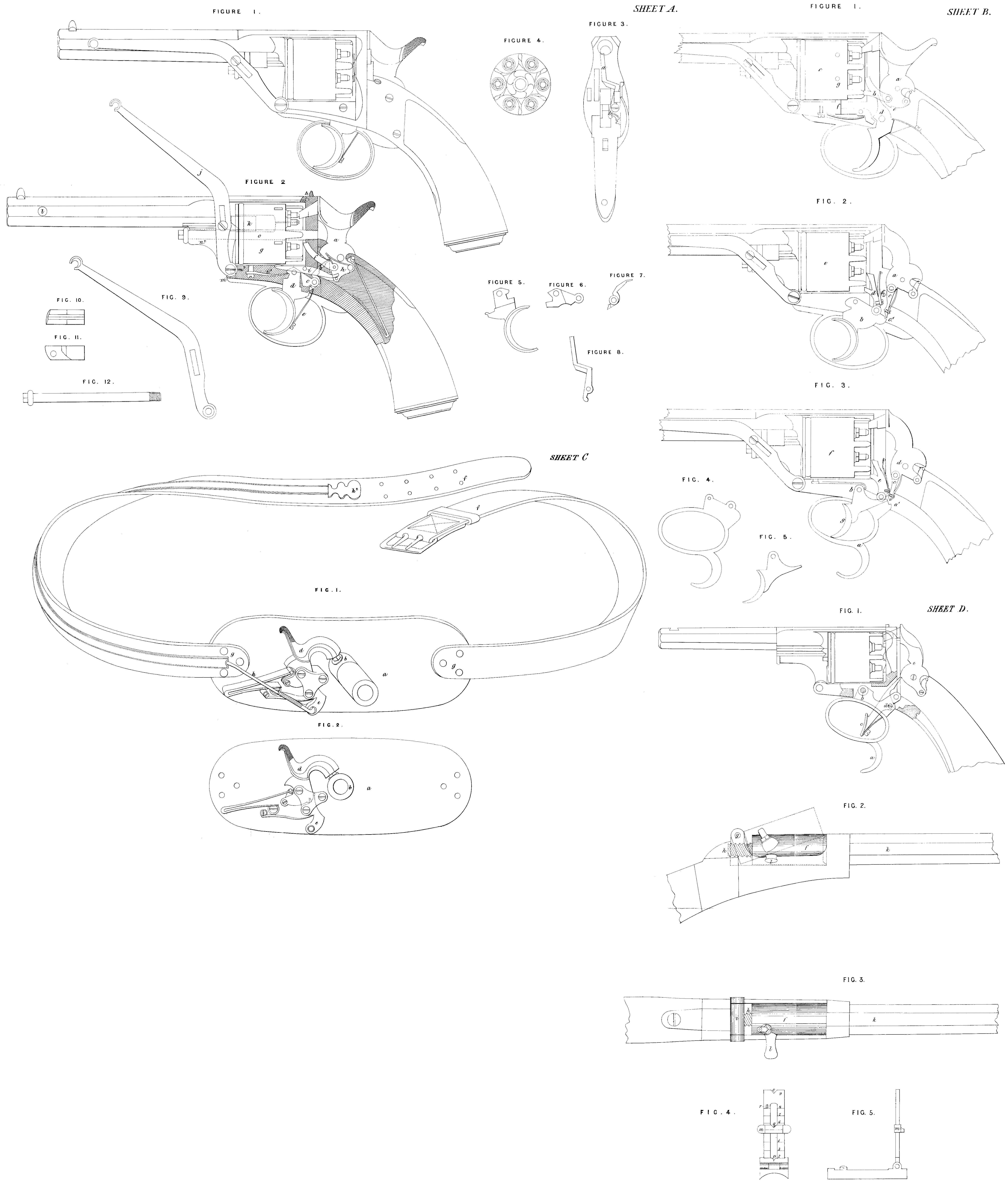
Figure 1, Sheet A, represents in side elevation a repeating pistol, constructed according to this part of my Invention; and Figure 2 represents the same in vertical longitudinal section. A sear b is connected with the trigger d by means of an arm or lever c turning upon the same centre as the said trigger d. The arm c is shown separately in Figure 6. The sear b is pressed against the lower end or tumbler of the cock a by the spring e, and is thereby made to engage in one of the two bents on the said tumbler. When the cock a is raised by the thumb, the sear b engages in the lower bent of the tumbler, and the cock a is thereby held at full cock. By pressing the trigger d, the sear b is disengaged from the bent, and the cock falls by the action of the main-spring. When the cock is not cocked by the thumb, the pressing of the trigger causes the sear b to raise the cock, and afterwards to liberate the said cock and discharge the fire-arm. The several parts of the lock being in the positions represented in Figure 2, the first effect of pressure upon the trigger d s to raise the cock a. The further pressure on the trigger causes the sear n to escape from under the shoulder or bent, under which it is represented engaged in Figure 2. The revolution of the chamber g is effected by means of a driver f on the lower end of the cock, which said driver is pressed to its bearing by the spring h. The chamber g is fixed during the discharge of the fire-arm by a lever bolt i, which-is made to engage with the chamber g when the fire-arm is about being discharged by means of a spring i’ pressing its end into a recess in the said chamber g. The said bolt i is disengaged from the chamber g when the cock is being raised by a pin on the lower end of the said cock.
Figure 4 represents the revolving chamber g in end elevation; Figure 5 represents the trigger d separately; and Figure 7 represents separately the sear b. My Invention consists, further, in the method of constructing the locks of single-action repeating fire-arms illustrated in Figure 1, Sheet B, of the accompanying Drawings. a is the cock, which, when raised by the thumb, causes the lifter b jointed to it to urge forward the revolving chamber c. The cock a, when raised, is maintained in its position of full cock by the upper end of the trigger d engaging in the bent e in the tumbler of the cock. When. the trigger is pressed it acts upon the lever f; forcing the upper end of the said lever into one of the recesses g in the revolving chamber c during the discharge of the fire-arm. The upper end of the trigger at the same time escaping from the bent e, the cock a falls and effects the discharge of the fire-arm.
My Invention consists, further, in the method herein-after described, and illustrated in Figure 2, Sheet B, of the accompanying Drawings, of constructing the locks of repeating fire-arms. A lever c on the cock a engage cock a is raised. Further pressure on the trigger b brings the lever c against a fixed stop f, by which the further motion of the lever c laterally is prevented. The bent c’ in the trigger consequently escapes from under the end of the lever c, when the cock a is liberated, and falling,discharges the fire-arm. The trigger carries a forked lever d, one branch of which carries round the chamber e through the proper distance, after which the lower branch engages with and fixes the said chamber e. I sometimes make the guard of a fire arm turn upon a centre, as illustrated in Figure 8, Sheet B, of the accompanying Drawings. The said guard a has a bent a’, with which the lever c engage and by pressing the guard ae it turns upon the centre b, and through the lever c, lifts the hammer d. By afterwards pressing upon the trigger g, the Said trigger presses against the lower end of the lever c, and disengages it from the bent a’, the cock d falls and discharges the fire-arm. The guard of the fire-arm, Figure 3, Sheet B, is represented separately in Figure 4, and the trigger is represented in Figure 5. I sometimes construct the mechanism for raising and liberating the cock in the manner illustrated in Figure1, Sheet D, of the Drawings.
The guard a turns upon the centre b; the said guard a carries the trigger c Jointed to its upper side at d. By pressing upon the moveable guard a, the cock e is raised, and by afterwards pressing upon the trigger c the upper end of the said trigger is disengaged from the cock e, which then falls and dis charges the fire-arm.
My Invention consists further in the manner of connecting the fixed barrel of revolving fire-arms to the body of the said fire-arms. This part of my Invention is illustrated in Figure 2, Sheet A, of the accompanying Drawings. A solid strap extends from the top of the breech end of the barrel over the revolving chamber to the top of the lock frame. Studs n on the end of the said strap engage in holes in the lock frame. A projection n² on the bottom of the breech end of the barrel is jointed by a peg or mortice m to the projecting front m² of the lower part of the lock frame. A screw bolt o, which
serves as the axis of the revolving chamber, is passed through the projection n² on the under side of the barrel, and by screwing into the lock frame holds the parts described together. The screw bolt o is represented separately in Figure 12. I sometimes apply a safety stop or bolt to repeating fire-arms to prevent the accidental discharge of the same. This part of my Invention is illustrated in Figure 3, Sheet A, of the accompanying Drawings. It consists of a lever a, the upper end of which is interposed between the head of the cock and the nipple. The trigger when pressed comes against the lower end b of the lever a, and moving the said lever laterally, causes its upper end to pass from over the nipple before the fall of the hammer. The fall of the hammer cannot discharge the fire-arm when my safety stop or bolt is used unless the trigger is pulled. The safety stop or lever a is represented separately in Figure 8. I construct the loading rods of repeating fire-arms in the manner illustrated in Figures 1 and 2, Sheet A, of the accompanying Drawings.
The said loading rod k (shown separately in Figures 10 and 11) is actuated by an arm or lever j-(shown separately in Figure 9); a pin on the top of the loading rod k engages in a slot in the arm or lever j, and by bringing the said lever j into the position represented in Figure 2, the loading rod k is made to enter one of the barrels of the revolving chamber g, and force the charge into the said barrel. Or the arm or lever j may actuate the loading rod by means of a transverse depression or groove in the loading rod, in which groove the armor lever j may engage.
My Invention consists further in the method illustrated in elevation in Figure 2, and plan Figure 3, Sheet D, of the accompanying Drawings, of making fire-arms which, like repeating fire-arms, load at the breech, but have not a repeating action. I make the chamber f in which the charge is placed turn upon a horizontal axis g, so that it can be raised out of the line of the barrel for the introduction of the charge, as indicated in dotted lines in Figure 2. The chamber f is connected to the axis g by means of a screw A on the closed end of the chamber f engaging in a screw box i carried by the axis g. The screw h has, by preference, a double or treble thread, so that when the chamber f is charged it may be made, by a partial rotation, to engage firmly with the fixed barrel k. The rotation of the chamber f is effected by means of the pin or projection. This part of my Invention is applicable to ordnance.
My Invention consists further in a. method of constructing the sights of fire-arms, illustrated in Figures 4 and 5, Sheet D of the Drawings; Figure 4 representing a front, and Figure 5 a side elevation of a sight constructed according to my Invention. I make the sliding portion m of the sight of such a thickness, that when at the fixed stop r it gives one elevation, the sight being turned down. When the sight is raised, it gives, by means of the angular notches o and p, at the top and bottom of the said sight, and another angular notch q on the slide m, four other elevations without consulting the graduations on the sight.
The last part of my Invention consists of a fire-arm to be used for personal defence, and which fire-arm I call an anti-garrotter. This part of my. Invention is represented in Figures 1 and 2, Sheet C, of the accompanying Drawings.
A plate of iron or other rigid material a has a small barrel b fixed perpendicular to it, together with a nipple cock and other appurtenances necessary to a fire-arm. The plate a is provided with straps f; f, secured to the plate a at.g. By means of the said straps secured round the waist, the fire-arm is secured to the back of the wearer. A cord h passes through a guide on one of the straps and terminates in a button h². On pulling the button h² and cord h the trigger e is disengaged from the cock d, which had been previously cocked, and the said cock d falling, discharges the fire-arm. The projectile from the barrel b wounding any one who may attack the wearer from behind.
Having now described the nature of my Invention, and the manner of carrying the same into effect, I wish it to be understood that I do not limit myself to the precise details herein described, and illustrated in the accompanying Drawings, as the same may be varied without departing from the nature of my Invention; but I claim as my Invention, —
Firstly, the methods of constructing the locks of repeating fire-arms, hereinbefore described, and illustrated in Figures 1, 2, 4, 5, 6, and 7, Sheet A, Figures 1, 2,8, 4, and 5, Sheet B, and Figure 1, Sheet D, of the accompanying Drawings.
Secondly, the safety bolt for repeating fire-arms to prevent their accidental discharge, herein-before described, and illustrated in Figures 8 and 8, Sheet A, of the accompanying Drawings.
Thirdly, the method of connecting the fixed barrel of repeating fire-arms to the body of the said fire-arms, as herein-before described, and illustrated in Figures 2 and 12, Sheet A, of the accompanying Drawings.
Fourthly, the method of constructing the loading rod of repeating fire-arms, herein-before described,and illustrated in Figures 1,2, 9, 10,and11, Sheet A, of the accompanying Drawings.
Fifthly, the method herein-before described, and illustrated in Figures 2 and 3, Sheet D, of the accompanying Drawings, of constructing breech-loading fire-arms and ordnance.
Sixthly, the method of constructing sights for fire-arms, herein-before described, and illustrated in Figures 4 and 5, Sheet D, of the accompanying Drawings.
Lastly, the method of constructing fire-arms for personal defence, hereinbefore described, and illustrated in Figures 1 and 2, Sheet C; of the accompanying Drawings.
In witness whereof, I, the said Henry Ball, have hereunto set my hand and seal, this Second day of August, in the year of our Lori One thousand eight hundred and fifty-eight.
HENRY BALL (L.S.)
Witness,
George Shaw.