
US 221145
UNITED STATES PATENT OFFICE.
A. EDWARD BARTHEL, OF DETROIT, MICHIGAN.
IMPROVEMENT IN LOCKS FOR FIRE-ARMS.
Specification forming part of Letters Patent No. 221,145, dated November 4, 1879; application filed January 16, 1879;
To all whom it may concern:
Be it known that I, A. Edward Barthel, of Detroit, in the county of Wayne and State of Michigan, have invented a new and useful Improvement in Fire-Arms, which is fully described in the following specification, reference being had to the accompanying drawings, in which—
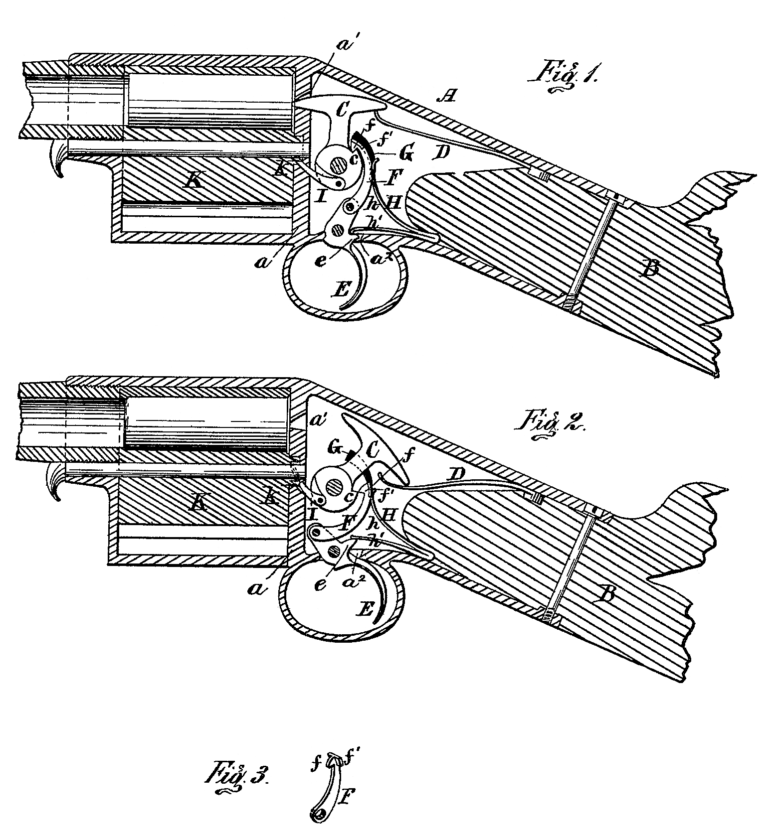
Figure 1 represents a longitudinal section of so much of a gun as is necessary to illustrate the construction and application of my improvements, the firing mechanism being shown in position after discharge and in readiness for cocking; Fig. 2, a similar view of the same, the firing mechanism being shown cocked and just ready for discharge; Fig. 3, a perspective view of the hook or dog by means of which the hammer is drawn back and cocked.
My invention relates to that class of: fire-arms in which the discharge is automatic and the firing mechanism self-cocking, or, in other words, is cocked by means of the trigger; and the object of my improvements is to simplify the firing mechanism, reduce the number of parts employed therein, and inclose the entire mechanism with the exception of the trigger within the stock-case.
The invention consists of various special devices and combinations of devices constituting the firing mechanism, all of which will be hereinafter fully described, and pointed out more distinctly in the claims.
in the drawings, A represents the casing for the reception of the stock B, which is inserted and secured in the ordinary manner. This casing is closed a little in front of the stock by the usual diaphragm, a, in which is the usual discharge-opening, a’; and in the under side of the casing is another opening, a^2, for the accommodation of the trigger, and there must also be an opening through the diaphragm for the passage of the cartridges into the firing-chamber if the arm is repeating; but with these exceptions the stock-case is without openings when all the parts of the arm are in place, and the exterior is entire and smooth except the trigger-guard, as shown in the drawings.
The front end of the stock Bis cut away, so that a closed chamber is provided in front of it within the casing. Within this chamber the firing-hammer C is pivoted, being arranged within the case, as shown in the drawings. In the drawings it is also shown as T-headed, though this construction is not necessary, as the space below the head may be filled or slotted, if desired. It is arranged so that the front end of the head will enter the discharge aperture a’ when the hammer is thrown forward for the purpose of firing the cartridge.
Back of the hammer is a leaf-spring, D, secured at its rear end between the casing and the stock, as shown in Fig. 2 of the drawings. The free end of the spring extends forward and rests upon the under side of the rear portion of the hammer-head. It is evident, therefore, that the force of this spring is constantly position shown in Fig. 1 of the drawings, and that when the hammer is swung back, thereby depressing the spring, as shown in Fig. 2 of the drawings, it will, so soon as released, be immediately thrown forward forcibly by the action of the spring, and thereby discharge the cartridge if one is placed within the firing-chamber.
The lower end of the hammer is in circular form, and is provided with a notch or hook, c, on the rear side thereof, the contour of this portion from the extreme outer edge of the hook-projection being in the form of a volute.
The trigger E is pivoted to the case just with in the opening a^2, and in rear of and a little below the pivot is provided with a projection, e. A hook or dog, F, something like a link, is pivoted at its lower end to the upper end of the trigger inside of the stock-case. This dog is curved in form, and at its upper end is provided with a hook, f, adapted to engage with the look on the hammer.
Lugs f’ extend outward on each side of the upper end of the dog, and are arranged to travel in curved guide-slots G, formed in the material on each side of the log, and just behind the hammer. These guide-slots are curved in form, and the front face thereof must be eccentric to the pivot of the hammer, and arranged so that as the slot extends downward it recedes from this pivot.
The other face of the slot may be either concentric with or eccentric to the hammer-pivot; but in either case the slot must be sufficiently wide to permit the hook on the dog to move backward as it is projected upward.
A vibrating leaf-spring, H, is secured at its doubled end between the stock and casing, as shown in the drawings. The upper branch, h, extends forward, and is bent upward, so as to rest upon the upper portion of the dog F. The lower branch, h’, is extended directly forward, and its end rests upon the upper side of the projection e on the trigger.
Now, it is evident that when these devices above described are in the position shown in Fig. 1 of the drawings the dog is engaged with the hammer, and the spring l presses directly against the former. If, now, the trigger is pulled backward, the dog will be pulled downward, thereby oscillating the hammer in a backward direction, as shown in Fig. 2 of the drawings; but at the same time the hook on the end of the dog will be gradually forced off from the hook on the hammer by the action of the eccentric guide-slot until at length at the lower end of the slot it is entirely disengaged from the hammer, which is then immediately thrown forward by the action of the spring D, and explodes the cartridge, as above described, thus being automatic in its action. The vibration of the trigger and downward movement of the dog also compresses both branches of the spring H, as shown in Fig. 2 of the drawings, so that the moment the hammer springs forward and the trigger is released by the finger the spring h will throw the latter forward again into the position shown in Fig. 1 of the drawings, and the dog will be thrust upward, the widening of the upper end of the guide-slot permitting it to ride the projecting hook om the hammer, so as to again engage with the latter, and the engagement is made sure by the spring h pressing against the upper end of the dog. The piece may there fore be fired as rapidly as the trigger can be worked by the finger, both the discharge and the engagement of the dog and the hammer being effected automatically.
It will be seen that all the parts of the firing mechanism except the lower end of the trigger are entirely within the stock-case, and are therefore protected perfectly, while the case is smooth without, and there is no danger of premature discharge by the hammer catching on some obstruction accidentally, as when it projects outside of the case.
The springs are secured without screws, as shown in the drawings, though the latter may be employed, if desired, and the two springs h h’ may be made separate from each other instead of in one piece, as described and shown.
The mechanism thus far described is adapted to a single cartridge-chamber.
If it is desired to use several revolving chambers, a pawl, I, is pivoted to the hammer, and the cylinder K, provided with chambers, is mounted, as usual, in the forward end of the case, and is provided with the usual ratchet k, with which the pawl I engages to turn the cylinder when the hammer is turned backward.
Instead of the guiding-slots or lugs on the dog, a cam-slot of suitable form may be made in the dog, and a pin inserted through the case into and through the slot in the dog.
Another modification in the device for guiding the dog may be made by making a guiding cam-slot on the hammer itself, and a pin or lug on the dog which works in this cam-slot.
Instead of the automatic devices above described, devices may be used for holding the hammer in position when cocked, if desired; but these would necessitate the use of another trigger, and would complicate the mechanism, thereby making it much less desirable. The great objection to self-acting mechanism, especially for rifles and sporting-guns, has been the large number of parts employed and the complicated nature of the mechanism.
It will be seen that in my improvement there are only five pieces, including the springs, with the addition of one more piece when a revolver is used, and the entire mechanism is so extremely simple that the objection mentioned above is entirely obviated.
The improvement may be applied to pistols and guns of all descriptions, and, with a suitable cartridge-magazine, the discharge of the piece may be effected with great rapidity.
Some of the devices may be modified in construction, and, so far as the inclosing of the discharging mechanism within the stock-case is concerned, I do not limit myself to any particular devices.
For the purpose of greater security, a suitable device may be added to lock the trigger when in the position shown in Fig. 1, or pulled a little back from this position, so that the hammer cannot be cocked and a discharge effected until the trigger is released.
A device may also be applied to the hammer by means of which it may be cocked without the use of the trigger, if desired, and such a device in the shape of a thumb-crank, or some similar device, may be found useful in a simple breech-loader for the purpose of holding the hammer back while the cartridge is inserted. Of course a shell-extractor is necessary to the efficient working of my improved firing mechanism, and for this purpose I propose to use any of the well-known extractors, which may be readily applied to my mechanism with out particular description here.
Having thus described my invention, what I claim as new, and desire to secure by Letters Patent, is—
1. An oscillating discharge-hammer provided with a hook or notch, in combination with a hooked link or dog, a curved guide for the hook end of the link, eccentric, or partly so, to the center of motion of the hammer, a spring trigger pivoted to the link, and a spring acting on the hook to cause it to engage with the hammer, substantially as described.
2. An oscillating automatic discharge-hammer provided with a hook or notch, in combination with a hooked link. or dog, a guide for the link-hook, eccentric to the hammer-pivot, a trigger pivoted to the link, and a spring constructed and arranged to act on both link and trigger, whereby cocking and discharge are effected by a single trigger, substantially as described.
3. The oscillating hammer C, in combination with the leaf-spring D, hooked dog F, trigger E, and branching spring H, arranged and operating substantially as described.
4. The trigger E, in combination with the dog F, provided with side lugs, f’, and pivoted to the trigger, and the eccentric guide-slots G, substantially as described.
5. The trigger E, in combination with the pivoted dog F, eccentric guide-slots G, oscillating hammer C, pawl I, pivoted to the hammer, and revolving chamber-cylinder K, provided with a ratchet, k, all constructed, arranged, and operating substantially as described.
A. EDWARD BARTHEL.
Witnesses:
Jno. C. Macgregor,
W. C. Corlies.