
US 469387
UNITED STATES PATENT OFFICE.
ANDREW FYRBERG, OF WORCESTER, MASSACHUSETTS.
COMBINED SEAR AND REBOUND CATCH FOR REVOLVERS.
SPECIFICATION forming part of Letters Patent No. 469,387, dated February 23, 1892.
Application filed September 9, 1891. Serial No. 405,177. (No model.)
To all whom it may concern:
Be it known that I, ANDREW FYRBERG, a citizen of the United States, residing at Worcester, in the county of Worcester and State of Massachusetts, have invented a new and useful Improvement in Revolvers, of which the following, together with the accompanying drawings, is a specification sufficiently full, clear, and exact to enable persons skilled in the art to which this invention appertains to make and use the same.
The object of my present invention is to provide a simple and efficient lock mechanism for revolvers, in which a sear and rebounder integral with each other or formed in a single piece is employed for operation in combination with the hammer and trigger, as more fully hereinafter specified.
This object I attain by mechanism the nature of which is illustrated by the drawings and explained in the following description, the particular subject matter claimed being hereinafter definitely specified.
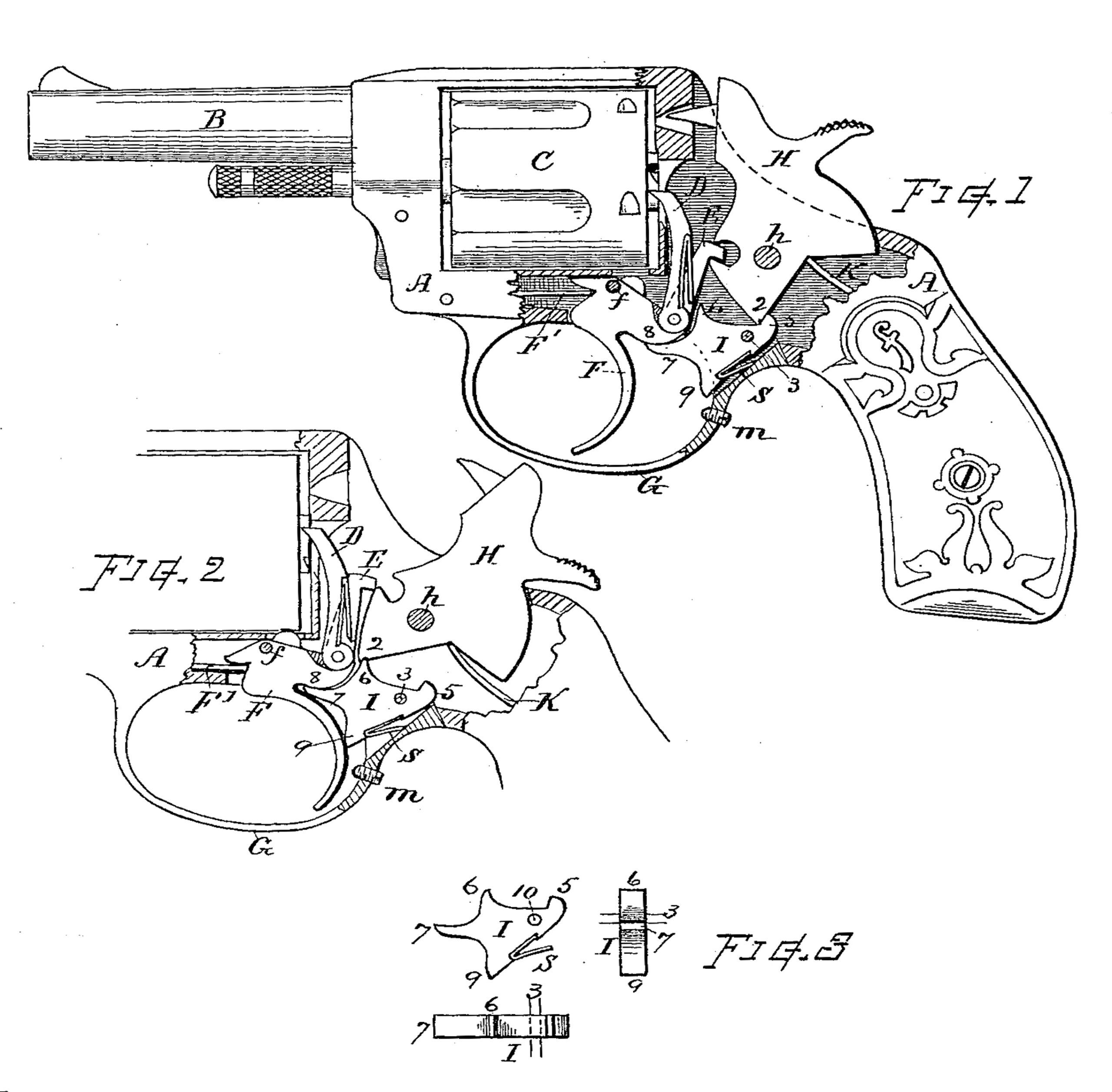
In the drawings, Figure 1 is a side view of a revolver embracing my invention, the side of the frame removed to reveal the working parts, the hammer standing at the position of the rebound. Fig. 2 is a view showing the position of “full-cock,” the hammer held back by the sear and ready for discharge by pressure on the trigger; and Fig. 3 shows, by side, front, and top views, the form of my compound integral rebounder and sear separate from the revolver.
In referring to parts, A denotes the stock or frame; B, the barrel; C, the cylinder; D, the pawl or rotating hand; E, the lifter; F, the trigger fulcrumed on the pin f and pressed forward by the spring F’; G, the guard; H, the hammer, and I the compound rebounder and sear.
The parts which are not herein particularly described may be understood as being of the usual or any suitable construction.
The hammer is pivoted, as at h, to be actuated by the mainspring K in the usual manner, and its lower end or tumbler is formed with an angle or point 2, relatively located, as shown, and having a slight notch or transverse indent in the rear side thereof closely adjacent to the apex of the angle.
The piece I, constituting the rebounder and sear, is disposed within the recess in the rear part of the guard and pivoted on the pin 3 beneath the hammer. Said piece I is shaped as illustrated, with a rebound lug 5 at its rear end that engages the angle 2 of the hammer when the hammer is down, an upwardly extended point 6, that serves as a sear for engaging the notch on the hammer-tumbler when the hammer is cocked by the thumb, a forwardly-projecting end 7, that works in conjunction with the rounded body 8 of the trigger for exerting the rebound leverage, and a downwardly-extended point 9, against which the back of the trigger presses for tripping the sear when the trigger is pulled for discharging the fire-arm. The several lugs or points 5, 6, 7, and 9 are all formed integral or on a single piece of metal and disposed thereon in the relative positions, substantially as shown. A hole 10 is formed through the piece for the fulcrum-pivot 3. The back of the trigger is recessed to afford space for the point 7 to enter, as indicated. A recess is formed in the lower rear edge of the piece I, and a spring S is confined therein, which expands against the metal of the guard and thus normally presses upward the piece I in opposition to the movement imparted thereto by the trigger in its contact therewith. If preferred, a coiled-wire spring may be used in lieu of this flat spring for elevating the piece I. Below the end 9 a screw-threaded stud is fitted in a threaded opening through the guard G, which stud serves as a regulating stop for the backward movement of the trigger, so that the sear can be forced from its notch and the movement arrested before the rebounder-lug is raised to a position where it would be struck by the angle 2 while the hammer is making its discharge movement.
The adjusting-stud m can be omitted in some instances, as on common cheap revolvers; but where fine and nice adjustment is desired the adjusting-stud is preferably used.
In the operation, when the hammer is drawn back by the thumb, the angle 2 at its lower end swings forward to a position over the sear-point 6, which latter catches into the notch at the rear of the angle and holds the hammer cocked. As the hammer moves back, the trigger is moved by the engagement of the lifter E to the position shown in Fig. 2. With the parts in this position they are ready for discharge. The trigger now being pressed back, its rear side, acting against the point 9, swings down the piece I and throws the sear-point 6 from the notch, allowing the hammer to be thrown down by the mainspring K. When the hammer is down, the angle 2 rests very close to but not in actual contact with the rebounder-lug 5. Then as the trigger is swung forward to its normal position the rounded part 8, acting against the point 7, depresses said point and swings the piece I, causing the rebounder-lug 5 to press forward the angle 2 and carry the hammer to the rebound position. (See Fig.1.) Automatic action is effected in the usual manner by simply pulling back the trigger.
I claim as my invention herein to be secured by Letters Patent—
1. A pivoted rebounder and sear formed integral with each other, in combination with the hammer, trigger, and cylinder-actuating devices in a revolving fire-arm, substantially as set forth.
2. The sear and rebounder formed integral or of a single piece fitted with the rebound-lug 5, sear-point 6, lever-point 7, and throw-off point 9, and pivotally supported on a pin 3 at the rear end of the guard, and the spring S, in combination with the hammer, having the angle 2, fitted with a sear-notch thereon, and the trigger having the rounded body 8, substantially as and for the purposes set forth.
3. The combination, substantially as described, of the integral rebounder and sear pivoted within the guard, the hammer having the angle and notch for engaging with said rebounder and sear, the trigger having the rounded head and rear surface that works in conjunction with said rebounder and sear, and the adjusting-stud m, fitted in the guard at the back of the trigger, for the purposes set forth.
Witness my hand this 5th day of September, A. D.
ANDREW FYRBERG.
Witnesses:
CHAS. H. BURLEIGH,
SIMEON E. KING.