
Britain 921
A.D. 1857 — N° 921.
Repeating Fire-arms.
LETTERS PATENT to Alfred Vincent Newton, of the Office for Patents, 66, Chancery Lane, in the County of Middlesex, Mechanical Draughts man, for the Invention of “IMPROVEMENTS IN REPEATING FIRE-ARMS.” A communication.
Sealed the 11th September 1857, and dated the 2nd April 1857.
PROVISIONAL SPECIFICATION left by the said Alfred Vincent Newton at the Office of the Commissioners of Patents, with his Petition, on the 2nd April 1857.
I, ALFRED VINCENT NEWTON, of the Office for Patents, 66, Chancery Lane, in the County of Middlesex, Mechanical Draughtsman, do hereby declare the nature of the said Invention for “Improvements In Repeating Fire-Arms,” to be as follows:—
The general object of these improvements is to obtain in revolvers greater readiness of operation, durability, and facility for repair, combined with elegance and compactness of form; but the more special object has been to provide for greater convenience, quickness, and certainty in the operations of loading and firing under the comparatively difficult and hitherto neglected contingencies of being in action on horseback, or in a boat; and, furthermore, to avoid the fouling of the lock by the smoke and gas resulting from the discharge, which is so common to revolvers in general.
These improvements are effected by certain improvements in the details of the arm, which I will now briefly point out. The rotating breech cylinder is surrounded and partly enclosed in a “casque” of a cylindrical form. This “casque” extends forward as far as the front face of the cylinder, and to its front is attached a transversely hinged apron piece, in which the barrel is screwed. A self-acting spring clamp, attached to the barrel, and projecting rearward, catches into a notch in the casque, and thus holds the hinged apron piece and the casque securely together. To prevent the straining or breaking of the spring clamp, a check pin or screw is provided, which stands up from the barrel, and prevents the spring being bent back or strained out of position. In the revolving cylinder grooves or shoulders are made, against which a safety screw projecting through the casque bears, for the purpose of preventing the cylinder from dropping out of place when the apron piece is turned
down.
The revolving shaft, through which the cylinder derives motion from the driving wheel within the lock, is provided with a button head, in advance of the bearing of the said shaft, such button head and a portion of the said bearing fitting into a central cavity in the rear end of the cylinder beyond the reach of the fire from the cones, thereby excluding all fire, smoke, and gas from the lock. The chambers of the cylinder are made with a conical seat to receive the ball, and in the rear of this seat the bore of the chambers is diminished.
The pawle which acts on the ratchet wheel for revolving the cylinder is connected to the rear end of a dog or lever, hinged to the heel of the hammer, and this dog, being itself operated by the trigger, will cause the pawle to revolve the cylinder. In combination with the dog, or its equivalent, by which the hammer is connected with the trigger for cocking, is an adjustable tripping screw, which disconnects the dog from the sere of the trigger sooner or later, as may be required. The driving pawle extends backward beyond its connection with the downward extension or heel of the dog, and connects with the main spring, whereby the main spring is made to serve as a pawle spring. The dog or lever is employed to act in combination with locking notches in the driving wheel, for the purpose of locking fast the cylinder at the proper position for discharge. On that part of the head of the trigger behind the sere is a screw projection, which is arranged to operate, in combination with a projection on the heel of the hammer and with the sere and dog, for the purpose of preventing the immediate fall of the hammer, when the dog is thrown of the sere of the trigger, to lock the revolving wheel, and retain the hammer on “cock” in a raised position, so as to afford an opportunity of taking deli berate aim. A sight hole is formed through the hammer to allow of a point blank aim over a fixed sight on the barrel being taken when the hammer is cocked, at the same time that the nick in the top of the hammer serves as an elevated sight, so that both sights are always ready when the hammer is cocked.
SPECIFICATION in pursuance of the conditions of the Letters Patent, filed by the said Alfred Vincent Newton in the Great Seal Patent Office on the 2nd October 1857.
TO ALL TO WHOM THESE PRESENTS SHALL COME, I, Alfred Vincent Newton, of the Office for Patents, 66, Chancery Lane, in the County of Middlesex, Mechanical Draughtsman, send greeting.
WHEREAS Her most Excellent Majesty Queen Victoria, by Her Letters Patent, bearing date the Second day of April, in the year of our Lord One thousand eight hundred and fifty-seven, in the twentieth year of Her reign, did, for Herself, Her heirs and successors, give and grant unto me, the said Alfred Vincent Newton, Her special license that I, the said Alfred Vincent Newton, my executors, administrators, and assigns, or such others as I, the said Alfred Vincent Newton, my executors, administrators, and assigns, should at any time agree with, and no others, from time to time and at all times thereafter during the term therein expressed, should and lawfully might make, use, exercise, and vend, within the United Kingdom of Great Britain and Ireland, the Channel Islands, and Isle of Man, an Invention for “Improvements In Repeating Fire-Arms,” being a communication from abroad, upon the condition (amongst others) that I, the said Alfred Vincent Newton, by an instrument in writing under my hand and seal, should particularly describe and ascertain the nature of the said Invention, and in what manner the same was to be performed, and cause the same to be filed in the Great Seal Patent Office within six calendar months next and immediately after the date of the said Letters Patent.
NOW KNOW YE, that I, the said Alfred Vincent Newton, do hereby declare the nature of the said Invention, and in what manner the same is to be performed, to be particularly described and ascertained in and by the following statement, reference being had to the Drawing hereunto annexed, and to the letters and figures marked thereon (that is to say):—
This Invention, as communicated to me by my foreign correspondent, is designed to obtain in revolvers greater readiness of operation, durability, and facility for repair, combined with elegance and compactness of form; but the more special object has been to provide for greater convenience, quickness, and certainty in the operations of loading and firing, under the comparatively difficult and hitherto neglected contingencies of being in action on horseback or in a boat; and, furthermore, to avoid the fouling of the lock by the smoke and gas resulting from the discharge.
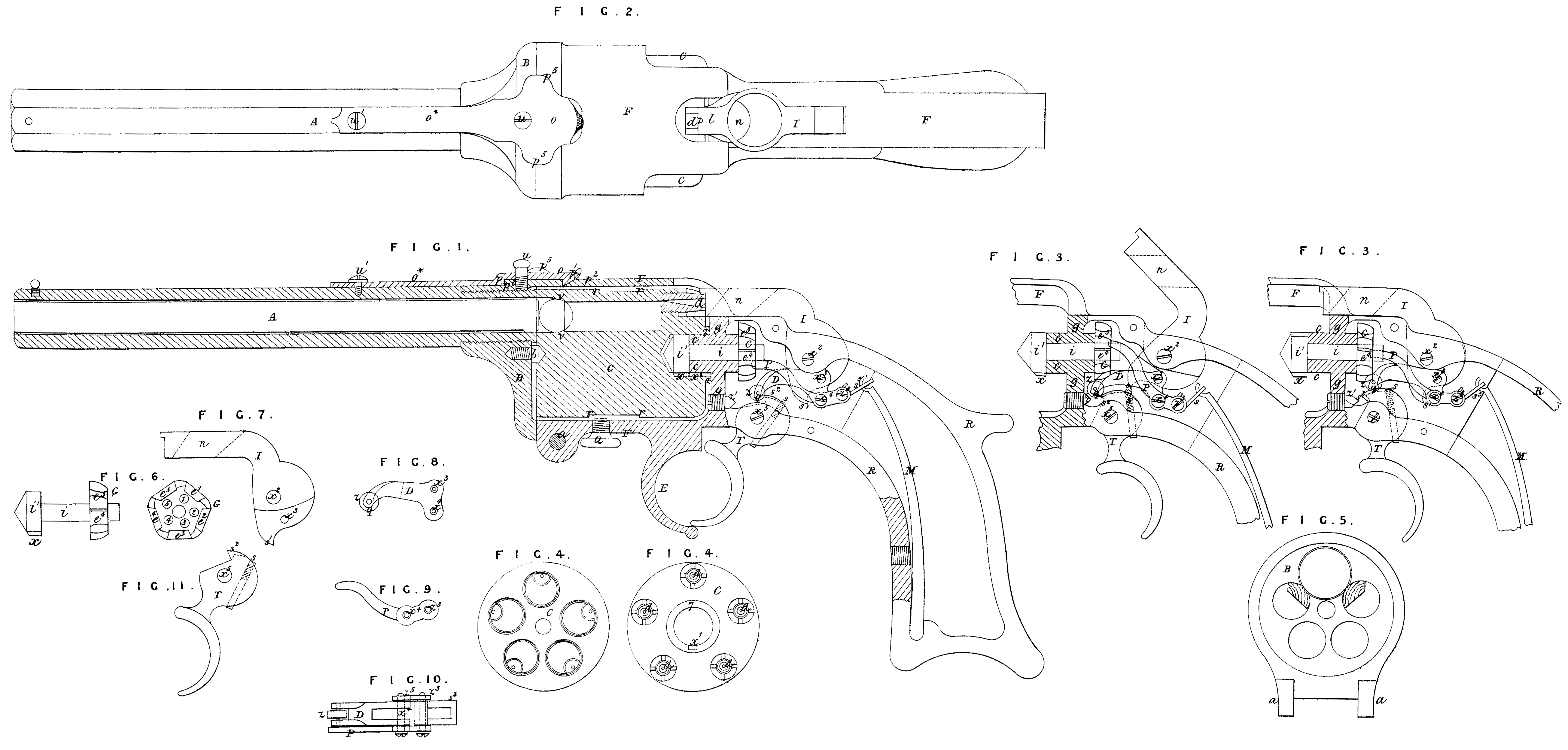
The Invention is illustrated in the accompanying Drawing, in which Fig. 1 is a longitudinal section of a “revolver” pistol with the improvements applied thereto; Fig. 2 is a top view of the same. Figures 3 and 3 * are interior views of the lock, the former exhibiting it in its condition before and the latter in its condition after the discharge. Fig. 4 is a front end view, and Fig 4* a rear 10 end view, of a revolving chambered cylinder; Figures 7, 8, 9, 10, and 11 are detail views, that will be found herein-after described.
A in Figures 1 and 2 is the barrel, screwed into an apron piece B, (of which Fig. 5 is an interior face view,) binged at a to the lower part of a “casque” F, of cylindrical form, which surrounds and partially encloses the revolving chambered cylinder C, and constitutes holder or receptacle for it while being loaded, thus affording great convenience for loading with loose powder. With a view to the employment of loose powder, and the prevention of the crushing of the grains thereof, and its too tight packing in the chambers by the ramming in of the balls, the chambers are constructed as shewn in Fig. 1, that is, they are first bored a trifle smaller than the bore of the barrel and then bored from the mouth inwards to a sufficient distance to receive a spherical ball of such size as to “slug” in rifle grooves in the barrel; such a tool being used for this larger bore as will make a seat v, v, of the form of a portion of a sphere to receive the ball, in the manner shown by red outline in the aforesaid Figure. The smaller portion of the bore is of sufficient capacity to contain the charge of powder, and when charged, the ball is placed in the mouth and rammed hard down upon the seat v, v, so as to make it expand towards the sides of the chamber sufficiently to make it fit tightly therein without packing or crushing the grains of powder. When the chambers are to be loaded with ball cartridges they should be constructed in the usual manner. The “casque” F is a part of the same casting as the frame R of the stock, the trigger guard E, and the recoil shield g; it extends forward as far as the front face of the cylinder C. The apron piece B is locked to the “casque” at the top, to lock the barrel and cylinder together in condition for firing, by a clamp O, which is attached to or forms part of the same piece of metal with a spring O*, that is fastened to the barrel by a screw u^1, or by any other suitable means. One lip p^1 of this clamp hooks into a notch or opening p^2 made in the top of the casque, and the other lip p fits against a shoulder p^3 on the apron piece, as shewn in Fig. 1, and thus the said clamp performs the duty of confining the apron and casque together independently of any aid from the spring O*, which is only used to attach it, and to bring it down into its place. Ears p^5, p^5, are made on the sides of the clamp to take hold of to lift the lip p^1 out of the notch p^2 for the purpose of liberating the apron piece B, so that the letter with the barrel can be turned down on its hinge a to leave the chambers of the cylinder fully exposed for convenience of loading. A stop screw u passes through a hole in the clamp O and screws into the top of the apron piece B, and serves to prevent the straining or breaking of the spring O* by lifting it higher than is necessary to enable the lip p^1 of the clamp to clear the notch or opening p^2. To insure the clamp 0 coming into operation to lock the barrel when the apron piece and barrel are raised, the rear lip p 1 is bevilled on its back side, so that when it meets the front of the casque it rises and slides over it, and snaps into the notch or opening p^2, and hence is self-acting. The detachment of the cylinder from the casque cannot, however, be effected when the apron piece is turned down, till the point of a screw Q, which may be termed the “safety screw,” is withdrawn from a groove r, r^1, (see Fig. 1,) that is turned round the exterior of the cylinder. This groove is so wide that when the apron piece is turned down, the safety screw Q will, while its point is in the groove, allow the cylinder to slide forward a short distance for convenience of capping the nipples d, d. Instead of having the screw in the casque, and a groove r, r^!, on the cylinder, the screw may be on the cylinder and the shoulders on the casque, which would be equivalent. The front end of the cylinder C turns on the point of a centre screw b, which is secured in the apron piece B, and its rear end turns on a hollow cylindrical projection c, which extends forward from the recoil shield g. The recoil bearing of the cylinder consists of an annular projection 7, formed on the rear end thereof, around the stationary projection c of the recoil shield. The hollow projection c forms a part of the bearing for the revolving shaft i, which imparts rotary motion to the cylinder. This shaft i carries at its rear end the revolving and locking wheel G, and at its front end it has a button i^1, of the same size as the exterior of the projection c, fitting into the cavity which is made in the centre of the rear of the cylinder to receive it and the projection c. The button i^1 fitting close up to the face of the projection c forms a joint that is beyond the fire of the cap, and prevents any smoke finding its way round the revolving shaft into the lock to foul it, which is an evil common to revolvers as heretofore con structed. This button i^1 is furnished with a feather X, fitting easily in a groove a x^1 in the cavity in the rear of the cylinder, and hence, when the wheel G, shaft i, and button i^1 revolve, the cylinder C must revolve with them. In the face of the wheel G, of which a view is given in Fig. 6, there are circular indentations 1, 2, 3, 4, and 5, arranged at equal distances apart, in a circle described from the centre of the wheel, and corresponding in number with the number of chambers in the cylinder C, which indentations serve as the equivalents of so many ratchet teeth in receiving the point of a pawl P, connected to and operated by the trigger T, whereby the necessary motion to produce the revolution of the wheel G is obtained. This pawl, which, besides being shewn in Figures 1, 3, and 3 *, is shewn in the detail views in Figures 9 and 10, is not jointed directly to the trigger, but is connected by a pin x^4 at some distance from its rear end with a dog D, which is connected by a joint pin x^3 with the tumbler of the hammer I, and which also serves the two purposes of transmitting motion from the trigger to cock the hammer and of locking the wheel G during the discharge of each chamber. The last mentioned part of its duty is performed by its entering into one of a series of notches e^1, e^2, e^3, e^4, e^5, corresponding in number with the chambers made in the edge of the said wheel. The dog D is shewn detached in Fig. 8, and in Fig. 10 it is shewn connected with the pawl P, the former exhibiting a side view and the latter a top view. It has a look q at its front extremity to engage with a sere s^2 on the trigger T, and has also attached to its front extremity a friction roller 2, which is intended to run up the conical or otherwise inclined point of an adjustable screw z^1, which is inserted in the recoil shield for the purpose of liberating or tripping off the hook q from the sere s^2 of the trigger, The screw z^1 being adjustable, enables the dog to be liberated sooner or later, as the case may require. The trigger, which is shewn detached in Fig. 11, has its upper part in the form of an excentric segment, and some distance in rear of the sere s^2 there is a projection s, by preference a screw, (as shewn in Figures 1, 3, 3 *, and 11,) which admits of adjustment. This projection s is intended to work in combination with a projection s^1, on the bottom of the tumbler or heel of the hammer I, in a manner that will be presently described. x^5 is the pin constituting the centre of motion of the trigger, and x^2 is a pin constituting the centre of motion of the hammer. The hammer I has a taper hole n through its head, which when it is at full cock comes horizontally in the line of sight, so that point blank aim can be taken over a fixed sight on the barrel; and it has a nick l in the top (see Fig. 2), which serves as an elevated sight, so that either sight is at all times ready when the hammer is 35 cocked. M is the main spring, connecting by a stirrup s^3 and a pin z^3, passing through the rear end of the pawl P. To make the dog sufficiently rigid in a lateral direction, the pin z^3 above mentioned, and the pin z^4 before mentioned, as connecting it with the dog D, are extended through a short link-like piece of metal z^5, (see Fig. 10,) which has the same form as the rear portion of the pawle, as separated by the dotted line in Fig. 9, and the dog D and stirrup s^3 fitting between the pawl and link z^5 prevent any twisting strain, and hence any tendency to a lateral movement of the pawl. The operation of firing the pistol is effected as follows:— When the trigger is pulled, the sere s^2 moves forward, and catching the hook q of the dog D, draws forward the dog, which, by its connection with the hammer, raises it, and by its action on the pawl P causes the point thereof, which is in one of the circular indentations in the face of the wheel G, to move upwards, and thus to cause the revolution of the said wheel, and consequently of the cylinder C. The simultaneous rotation of the wheel G and forward movement of the dog D brings one side of the head of the latter at the proper moment against the higher side of one of the locking notches e^1, e^2, &c. (see Fig. 6), and the rotation of the cylinder is thereby stopped, while at the same moment the under surface of the friction roller z of the dog is borne on the conical or inclined point of the adjustable screw z^1 and any further pull of the trigger forces the top of the head of the dog ( which is made of such shape as to fit snugly into the bottom of the locking notches) to the bottom of a locking notch, where upon the hook q, which has been slipping up off the sere s^2, escapes entirely therefrom. This escape would leave the hammer free to fall, but that it is prevented by the projection or screw point s of the trigger catching the projection s^1 of the hammer tumbler ( as shewn in Fig. 3 ) at the instant of such escape.. The reason for thus preventing the fall of the hammer is, that if it fell with the escape of the hook no deliberate aim would be permitted, owing to the uncertainty to the operator of the precise instant of the escape. The projection s continues to hold up the hammer so long as the trigger is held back, but as soon as the pressure of the finger upon the trigger is in the least degree slackened so as to allow it to move forward, the main spring, by its action on the tumbler of the hammer, draws the projection s^1 clear of the projection s, and the hammer being released, falls and effects the discharge. Thus, the instant of discharge is both known and controlled, and deliberate aim allowed. After the discharge, as the finger continues to relax its pull on the trigger, the downward pressure of the hook q of the dog D upon the then steeply inclined excentric upper portion of the trigger forces the latter back into the position shewn in Fig. 1, and causes the parts of the lock to assume the proper positions for another discharge by another pull of the trigger. The main spring in this weapon performs all the duties which in fire-arms of usual construction require several springs. By its connection with the rear end of the paul P through the stirrup s^3 it presses down the forward end of the pawl and thus holds it into the indentations 1, 2, 3, 4, 5 in the face of the revolving wheel G, and through the connection of the pawl P with the dog D at x^4 it presses down the forward end of the latter upon the trigger, and through the connection of the dog with the hammer at x^3 bears down the head of the hammer upon or toward the cones d, d.
The same construction and arrangement of all the parts, as is above described, may be applied to rifles, but as owing to the greater weight of a rifle barrel it would not be so convenient to have it arranged upon a hinge to turn down, provision may be made for loading the chambers through openings in the apron piece.
Having thus set forth the nature of the “Improvements in Repeating Fire-arms,” communicated to me from abroad, and explained the manner of carrying the same into effect, I wish it to be understood that under the above in part recited Letters Patent I claim,—
First, the combination of the “casque” F, extending forward as far as the 15 front face of the cylinder, and surrounding it with the transversely hinged apron piece B, substantially as set forth.
Second, the construction of the chambers, as illustrated in Fig. 1, and herein fully described, for the purpose of loading with loose powder and balls.
Third, the self- acting spring clamp O combined with the barrel apron 20 piece and casque, substantially as described.
Fourth, the check screw u applied as described to prevent the straining or breaking of the spring O* by the operation of the clamp O.
Fifth, the employment, in combination with the casque F and revolving cylinder, of the safety screw Q, and groove or shoulders r, r^1, for the purpose herein specified.
Sixth, providing the revolving shaft i, through which the cylinder derives motion from the revolving wheel within the lock, with a button head i^1 in advance of the bearing c, c, of the said shaft, such button head and a portion of the said bearing fitting into a central cavity in the rear end of the cylinder, beyond the reach of the fire from the cones, thereby excluding all fire, smoke, and gas from the lock.
Seventh, the combination with the dog D, or its equivalent, by which the hammer is connected with the trigger for cocking, of an adjustable tripping screw z^1, operating substantially as described, to disconnect the dog from the sere of the trigger sooner or later, as may be required.
Eighth, extending the rear end of the aforesaid dog, or its equivalent, down wards, from where it connects with the heel of the hammer, and jointing to the part so extended the pawl P, which acts on the revolving wheel of the cylinder, thereby causing the pull on the dog, or equivalent, by the trigger to operate the pawl to revolve the cylinder, substantially as herein set forth.
Ninth, extending the pawl backward beyond its connection with the down ward extension or heel of the dog, and connecting the main spring to the part of the pawl so extended, substantially as herein described, whereby the main spring is made to serve as a pawl spring.
Tenth, the arrangement of the dog D, or its equivalent, to act in combination with locking notches in the revolving wheel G, or its equivalent, for the purpose of locking fast the cylinder at the proper position for discharge, as herein set forth.
Eleventh, the projection or screw s on the part of the head of the trigger behind the sere, and the projection s^1 on the heel of the hammer, arranged to operate in combination with each other and with the sere s^2 and dog D, for the purpose of preventing the immediate fall of the hammer when the dog is thrown off the sere s^2of the trigger to lock the revolving wheel and retaining the hammer on ” cock, ” in the manner herein described, and illustrated in Fig 3, to afford opportunity for taking deliberate aim.
Twelfth, the construction of the hammer with an opening n, which when the hammer is cocked may be looked through for the purpose of taking point blank aim over a fixed sight on the barrel, at the same time that the nick in the top of the hammer serves as an elevated sight, so that both sights are always ready when the hammer is cocked.
In witness whereof, I, the said Alfred Vincent Newton, have hereunto set my hand and seal, the Second day of October, in the year of our 25 Lord One thousand eight hundred and fifty-seven.
A. V. NEWTON. (L.S.)
Witness,
J. W. Moffatt,
66, Chancery Lane.