
US 37961
UNITED STATES PATENT OFFICE.
ALBERT HALL, OF DAN WILLIE, IOWA.
IMPROVEMENT IN REVOLVING FIRE-ARMS.
Specification forming part of Letters Patent No. 37,961, dated March 24, 1863.
To all whom it may concern:
Be it known that I, Albert Hall, of Danville, in the county of Des Moines and State of Iowa, have invented certain new and useful Improvements in Revolving Fire-Arms; and I do hereby declare that the following is a full, clear, and exact description of the same, reference being had to the accompanying drawings, forming part of this specification, in which—
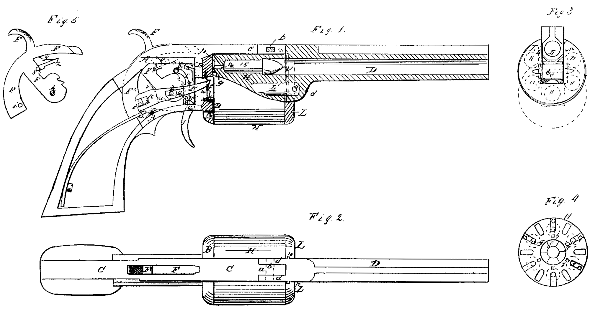
Figure 1 is a side view of a pistol with my improvements, representing it with the cap-plate of the lock removed to expose the interior and with the barrel and part of the cylinder in section. Fig. 2 is a top view of the same. Fig. 3 is a front view of the barrel and cylinder. Fig. 4 is a back view of the cylinder. Fig. 5 is a side view of the hammer.
Similar letters and numbers of reference indicate corresponding parts in the several figures.
The invention consists in a novel construction and arrangement of the several parts of the lock of a revolving fire-arm whereby the whole of the hammer, with the exception of the thumb-piece, is brought within the frame, and the arm, more especially if a pistol, is made more compact, and whereby the action of the trigger is rendered easier and more like that of a hair-trigger.
It also consists in the novel construction of and mode of applying a movable plate to provide for the loading of the chambers at the front of the cylinder and for confining the loads in the chambers after their insertion.
It also consists in the arrangement, in combination with such movable plate, of an opening in the lower part of the recoil shield to provide in reloading the chambers for the pushing out of exploded percussion-primers of peculiar construction, which are employed in the cartridges with which I propose to load the arm.
To enable others to make and use my invention, I will proceed to describe its construction and operation.
A is the frame, having made in the same piece with it the recoil-shield B, and having a portion, C, extended longitudinally over the cylinder to connect with the barrel.
D is the barrel, having on the lower part of its rear end a downward projection, c, for the reception of the front end of the axis-pin E, and on the upper part of the said end a rear ward projection, d, which is mortised for the reception of a tenon, a, formed at the front extremity of the portion C of the frame. The barrel thus constructed at its rear end is secured to the frame and recoil-shield partly by means of a key, b, inserted transversely through the mortise and tenon above mentioned, and partly by means of a pin, e, passing transversely through the projection c and the front part of the axis-pin, the rear end of the axis-pin being firmly screwed through the recoil-shield into the portion of the frame behind it.
The cylinder H has formed upon its rear end the usual ratchet, f, which is operated upon to produce its rotation, and outside of this ratchet there are provided in the said end a concentric circular series of holes, g g, corresponding with the number of chambers for the reception of the point of a stop-dog, y, by which the cylinder is locked with its chambers in line with the barrel.
F is the hammer, working within the frame on the fixed pin h, which is arranged much lower down in the frame than is customary. The outside of the head of this hammer is made in the form of an arc, concentric with its axis of oscillation, and a portion of the upper part of the frame A is made of corresponding form, so that the said head, working in a slot provided in that part of the frame, may be just flush with it, leaving no part of the hammer but the thumb-piece F’ projecting above the frame. The head of the hammer extends back some distance beyond the shank and the thumb piece, as shown at F^2, such extension serving to close the slot in the frame. When the hammer is down or forward, and serving also to carry a pin, j, through which the rotation of the cylinder is effected, and affording convenience for the application of the mainspring G, which presses against the rear extremity of such extension.
I is the sear, suspended from a pin, k, above the tumbler of the hammer, and extending downward nearly to the bottom of the portion of the frame in front of the hammer, having its lower end forked to receive a pin, l, which is carried by the trigger J, and having its tooth n at about the middle of its length. The trigger J is arranged to work in the usual position on a pin, In, and the trigger-spring p is applied substantially in the usual manner. The pin l is but a short distance from the pin m. The cock and half-cock notches in the hammer-butt are arranged farther forward than usual, to suit the position of the sear. This arrangement of the sear in relation to the hammer and in connection with the trigger brings a much greater leverage on the tooth of the sear than is done with other arrangements of the parts, and so makes the trigger work so easily that in drawing it the aim is not likely to be disturbed.
K is a lever through which the hammer operates to produce the rotation of the cylinder. This lever has provided in it a longitudinal slot, q, which fits to the pin h, and enables the said lever to move longitudinally as well as oscillate upon the said pin. The front end of the said lever is made of suitable form to enter the notches of the ratchet f and the rear end is forked, as shown at t in Fig. 1, to receive the pinion the back part of the hammer-head; but the space within the fork is wider than the pin i, so that the said pin may move up and down therein to some extent. On the inner or left-hand side of the said lever there is a projecting pin, u, against the back of which there bears a spring, v, which is secured to the back of the hammer-shank, and which tends to press the said lever longitudinally forward toward the ratchet f of the cylinder opposite to which the said lever is placed. The front end of the said lever works through a slot, w, in the recoil-shield, to act upon the teeth of the said ratchet. By the act of cocking the hammer the pin j is made to act upon the lower prong of the fork t of the said lever, and so to depress it and raise the front end, which is thus caused to act upon a tooth of the ratchet in the manner required to produce the rotation of the cylinder. As the hammer strikes, the rear end Of the lever is raised by the action of the pin j in its fork, and the front end moved down over a tooth of the ratchet, and after passing the front of the said tooth the said lever strikes the lower edge of the slot w in the recoil-shield, and the said edge being beveled, as shown at x in Fig. 1, and the point of the lever being beveled also, the lever in sliding down the bevel a is caused to move longitudinally backward far enough to clear the ratchet entirely, so that until the cylinder has been unlocked by the withdrawal of the dog y from one of the holes g g in the cylinder, as will be presently described, the lever in the recocking movement of the hammer will be prevented from rubbing against or catching in the ratchet. The play allowed to the pin j in the fork t prevents the lever from being moved at all during the first part of the cocking movement, and so assists in providing for the unlocking of the cylinder before the lever K comes into operation on the ratchet.
The stop-dog y is attached to a spring, y’, which is arranged within the frame A at the back of the recoil-shield, and at the upper end of this spring there is formed a hook, y^2. Attached to the hammer there is another hook, z, which, as the hammer commences to be drawn back to cock it, catches the said hook y^2 and draws it back, and so draws back the dog y from the hole g in the cylinder which it has previously entered to lock the latter. By the time the rotary movement of the cylinder has commenced, the hook z, having a partially-upward motion, escapes from the hook y^2, and lets the spring y’ carry forward the catch again into contact with the rear end of the cylinder; but the hole g having now passed by the position of the dog, the latter rests against the cylinder till the next hole g comes round to it, when it drops into the latter hole and stops the further revolution until the hammer has been let down and is again drawn back. As the hammer moves forward or falls to strike, the hook x is permitted to slip over the hook y^2 by reason of its being attached to the hammer by a pin-joint, 8. This joint is so constructed with a shoulder below its pin that the hook cannot drop below a certain position, though it is permitted to rise sufficiently to enable it to slip over the hook y^2, and the said hook z has applied to it a spring, q, which insures its engagement with the hook y^2.
L is the movable plate which covers all that portion of the front of the cylinder not covered by the barrel. This plate is of circular form corresponding with the cylinder, but has an opening corresponding inform with the rear end of the barrel, and the sides of this opening are grooved to fit easily to two small guide-tongues, 10 10, formed on the barrel, one of the said tongues and grooves being formed with a stop to prevent the plate from being drawn entirely off the barrel, but permitting it to be brought down to the position shown in red outline in Fig. 3, which leaves the front end of any one of the chambers 11 11 of the cylinder that may have been brought to its lowest position— that is to say, directly under the axis-pin— exposed through the opening in said plate, so that the charge can be inserted thereinto from the front.
The cylinder represented is constructed for firing metallic cartridges of peculiar construction, one of which is shown in Fig. 1, and for this purpose the rear portion of each chamber is bored smaller than the portion in front, which receives the bullet. This cartridge has attached to its rear end a small tubular primer, 14, which enters a vent, 12, in the rear of the chamber and is fired by the hammer striking into the vent through a slot, 13, provided therein. The metallic cartridge-shells 15 are blown out in firing, but the primers 14 remain in the vents until the chambers are reloaded, when they are pushed out through the small hole 16 in the lower part of the recoil-shield, such opening being exactly opposite the position in which the chambers are loaded.
What I claim as my invention, and desire to secure by Letters Patent, is—
1. The suspended sear I, constructed and arranged in combination with the hammer and trigger, substantially as herein specified.
2. The stop-dog y, arranged in rear of the cylinder within the frame and combined with the hammer by means of hooks y^2 and z, substantially as herein described.
3. The lever K, constructed and applied in relation to the cylinder and combined with the pin h, and with the extension F^2 of the hammer, substantially as and for the purpose herein specified.
4. The combination, with the so constructed and applied lever K, of the bevel x, at the bottom of the slot w in the recoil shield or frame, through which the said lever works, substantially as and for the purpose herein specified.
5. The plate L, constructed and applied in combination with the barrel and cylinder, substantially as and for the purpose herein specified.
6. The hole 16 in the recoil-shield below the frame, arranged in combination with the opening in the plate L, substantially as and for the purpose herein specified.
A. HALL.
Witnesses:
G. W. Reed,
Daniel Robertson.