
British 2107
LETTERS PATENT to John Piddington, of 53, Gracechurch Street, in the City of London, Patent Agent, for the Invention of “ Improvements in Revolvers and Revolving Fire-arms, and in Apparatus to be used therewith.”—*A communication from abroad by Albert Spirlet, Armurier, of No. 5, Quai de la Boverie, Liege, Belgium.
Sealed the 20th January 1871, and dated the 27th July 1870.
PROVISIONAL SPECIFICATION left by the said John Piddington at the Office of the Commissioners of Patents, with his Petition, on the 27th July 1870.
I, John Piddington, of 53, Gracechurch Street, in the City of London, Patent Agent, do hereby declare the nature of the said Invention for “Improvements in Revolvers and Revolving Fire-arms, and in Apparatus to be used therewith,” being a communication to me from abroad by Albert Spirlet, Armurier, of No. 5, Quai de la Boverie, Liege, Belgium, to be as follows:—
This Invention consists in a combination of parts and mechanism whereby revolving fire-arms are readily loaded, and the several parts held firmly in position during the discharge, whilst the expended cartridge cases are removed from the charge chamber or cylinder by a simple and at the same time strong and efficient extractor.
In applying these improvements the body of the pistol which carries the lock, hammer, and trigger arrangements, as also those for producing the rotary motion of the cylinder, is formed in a manner almost identical with that ordinarily used for revolvers, in which the cylinder is supported upon a pin or bar which passes through and is attached to both the body of the pistol and the enlargement on the under side of the barrel, but in which the barrel itself is not directly connected with such a body as that referred to, but, on the contrary, a strap or band is formed in a piece with the barrel, or attached thereto in any convenient manner, and continued in a rearward direction over the cylinder for a sufficient length, and so arranged as to form, with the upper part of the recoil surface of the body and a screw pin which passes through both, a strong hinge at right angles to the axis of the barrel, and upon which the barrel is free to turn, as hereafter described. On the under side of the barrel, and immediately in front of the cylinder or space which the cylinder is intended to occupy, is formed or attached a strong piece of metal, which extends to and abuts against the front end of that part of the pistol body which supports the trigger guard, and to which body this extension of the barrel is secured by a spring latch. By means of this latch and of the hinge the barrel and body of the pistol are firmly united, and are then almost equal in solidity to a pistol in which the body for the support of the cylinder is solid, and the barrel attached to the body by a screw formed upon its rear end, or in any other manner. Instead of fixing the pin or axis of the cylinder to the body alone, or to the body and the enlargement on the under side of the barrel, as is usual, the pin or axis upon which the cylinder rotates is arranged in such a manner that it is supported by the enlargement on the under side of the barrel, and consequently the cylinder with its pin or axi$ moves with the barrel upon the hinge at the upper part of the recoil surface, as already described, when the spring latch which secures the lower and prolonged limb of the barrel to the body is released, which is readily done by a quick pressure. But apart from its function as an axis upon which the cylinder is free to rotate, this pin has another and equally important function in connection with the extractor and ejector of the expended cartridge cases. On the rear face of the cylinder is formed a circular sinking to the depth necessary to receive the extractor, the thickness of which depends upon that of the rim or shoulder of the cartridge which it is formed to embrace, and which extractor is arranged to occupy about one-half of the circumference of the rim or shoulder, and consequently it has somewhat of a star-like form. The outward rim face of this extractor carries the ratchet by which the rotation of the cylinder is effected, and which may or may not be formed upon or with it. The forward part of the extractor is a tube, which externally has the same diameter as the interior of the cylinder which passes over the pin or axis, but this pin is necessarily reduced in order to pass through the tube of the extractor, and further the pin has a screw thread cut upon it, and a screwed cap, which is thus attached to the pin, has a solid end which when the piston is closed in position for firing enters a hollow formed for it in the recoil surface, and thus the cylinder rotates upon an axis supported at two points ; this pin or axis has an enlarged end or head which is prepared to slide upon the under side of the barrel. The pin and enlargement on the under side of the barrel are prepared to receive a spiral spring and telescope cover, so as to retain the extractor continually in position, unless when intentionally operated, and a small pin or guide is provided for the extractor, which enters the cylinder and maintains the extractor continually in the same position as regards the cartridge chambers and the cylinder.
The ignition of the cartridge may be effected by any convenient means, but it is preferred so to form the beak of the hammer that it shall pass through the recoil surface in a line with the igniting medium of the cartridge; and it is also sometimes preferred to form the hinge in such a manner that it shall on operating the motion of the barrel throw back the hammer to the half or safety bent, in which position it is maintained until operated by the trigger or by the hand. It is sometimes also preferred to use a set screw or other means of securing and maintaining the extractor and cylinder upon the pin or axis in the place of tha already described.
It is obvious that the details herein described may be modified to suit the requirements and without departing from this Invention, which is for a revolver or revolving pistol or other fire-arm in which the barrel with the cylinder and extractor, both operated upon the same pin or axis, is hinged by a strap or band to the upper part of the recoil surface of the body of the pistol, and is secured in position during the act of discharging the cartridges to the lower and forward portion of the body which supports the trigger and guard by a spring latch or catch acting either in the body of the revolver or in the extension on the under side of the barrel. By operating this spring latch the barrel with the cylinder and extracting arrangements is released and free to swing upon the hinge, whereby the chambers of the cylinder arc exposed to receive the cartridges, the hammer having been moved back by this operation sufficiently to be engaged in the half or safety bent. The cylinder being charged and the barrel and attached parts turned upon the hinge in the opposite direction until the extension of the barrel comes in contact with or against the lower and forward portion of the body, when the spring latch secures the whole in a solid position during the discharge, which may effected by any system of single or double action lock. The cartridges being discharged the operation of opening the arm, as abovo described, is performed, and the expended cartridge cases arc extracted and ejected from the chambers by simply pressing upon or striking the head of the pin or axis, which being free to move a restricted distance carries with it the extractor, and thereby the expended cartridge cases sufficiently far to entirely free them from the chambers of the cylinder. This being effected, and the head of the pin or axis released, the pin or axis with the extractor is returned into the original position by the spiral spring, and the arm as ready to be recharged. During these operations the cylinder is maintained in position by a slight groove equal in length to the cylinder, and formed in the strap or band of the barrel, or in any other convenient manner.
The mechanism of the lock ordinarily employed with revolving firearms for the rotation and adjustment of the cylinder, and for operating the dog or hammer for exploding the cartridge, is modified to suit the improvements which form the subject of this Invention, as will be well understood, but it is sometimes preferred to form the entire mechanism of the lock, or such parts thereof as may be necessary, upon a webb or thin plate of metal forming part of or securely attached to the body of the pistol, and occupying the centre or nearly so of the stock as may be most convenient.
In connection with revolving pistols constructed in accordance with this Invention, and in order to facilitate the operation of charging or of extracting the expended cartridge cases and recharging, a sheath or holster is sometimes employed, the same being formed of metal or leather, or of a combination thereof, or of other suitable material, so arranged as to form under ordinary circumstances a covering to the revolver, while it is also adapted to be used as an aid in the movements of opening the arm and withdrawing and expelling the expended cartridge cases and recharging in the following manner:—The pistol being held in the hand as for and after firing a smart blow of the spring latch upon the top of the holster will free the latch, when, by turning the butt of the pistol in the hand the barrel swings upon its hinge and exposes the breech end of the cylinder. On placing the barrel thus as itwere reversed in the holster the head of the pin upon which the extractor is mounted comes in contact with the outer side of the sheath, and a slight blow or pressure will effect the extraction and ejection of the expended cartridge cases, when the pistol is ready for recharging, after which, on withdrawing the barrel from the holster, a slight motion or turn of the hand swings the barrel in the reverse direction upon the hinge until the spring latch comes in contact with and closes in the body or extension of the barrel, and secures the barrel and moveable parts in position ready for firing. The revolver can thus, if desired, be operated by one hand only, and it will readily be understood that, for cavalry purposes especially, such a ready, simple, and efficient aid to the manipulation would be highly advantageous.
SPECIFICATION in pursuance of the conditions of the Letters Patent, filed by the said John Piddington in the Great Seal Patent Office on the 27th January 1871.
TO ALL TO WHOM THESE PRESENTS SHALL COME, I, John Piddington, of 53, Gracecliurch Street, in the City of London, Patent Agent, send greeting.
WHEREAS Her most Excellent Majesty Queen Victoria, by Her Letters Patent, bearing date the Twenty-seventh day of July, in the year of our Lord One thousand eight hundred and seventy, in the thirty-fourth year of Her reign, did, for Herself, Her heirs and successors, give and grant unto me, the said John Piddington, Her special licence that I the said John Piddington, my executors, administrators, and assigns, or such others as I, the said John Piddington, my executors, administrators, and assigns, should at any time agree with, and no others, from time to time and at all times thereafter during the term therein expressed, should and lawfully might make, use, exercise, and vend, within the United Kingdom of Great Britain and Ireland, the Channel Islands, and Isle of Man, an Invention for “ Improvements in Revolvers and Revolving Fire-arms, and in Apparatus to be used therewith,” being a communication to me from abroad by Albert Spirlet, Armurier, of No. 31, Quai de la Boverie, Li&ge, Belgium, upon the condition (amongst others) that I, the said John Piddington, my executors or administrators, by an instrument in writing under my, or their, or one of their hands and seals, should particularly describe and ascertain the nature of the said Invention, and in what maimer the same was to be performed, and cause the same to be filed in the Great Seal Patent Office within six calendar months next and immediately after the date of the said Letters Patent
NOW KNOW YE, that I, the said John Piddington, do hereby declare the nature of my said Invention, and in what manner the same is to be performed, to be particularly described and ascertained in and by the following statement, reference being had to the Drawings hereunto annexed, and to the figures and letters marked thereon, that is to say :—
This Invention consists in a combination of parts and mechanism whereby revolving fire-arms are readily loaded, and the several parts held firmly in position during the discharge, whilst the expended cartridge cases are removed from the charge chamber or cylinder by a simple and at the same time strong and efficient extractor.
In applying these improvements the body of the pistol which carries the lock, hammer, and trigger arrangements, as also those for producing the rotary motion of the cylinder, is formed in a manner almost identical with that ordinarily used for revolvers, in which the cylinder is supported upon a pin or bar, which passes through and is attached to both the body of the pistol and the enlargement on the under side of the barrel, but in which the barrel itself is not directly connected with the body. In these improvements a strap or band being formed of a piece with the barrel, or attached thereto in any convenient manner, is continued in a rearward direction over the cylinder for a sufficient length, and so arranged as to form with the upper part of the recoil surface of the body &nd a screw pin which passes through both, a strong hinge at right angles to the axis of the barrel, and upon which the barrel is free to turn, as herein-after described. On the under side of the barrel and immediately in front of the cylinder or space which the cylinder is intended to occupy, is formed or attached a strong piece of metal, which extends to and abuts against the -front end of that part of the pistol body which supports the trigger guard, and to which body this extension of the barrel is secured by a spring latch. By means of this latch and of the hinge the barrel and body of the pistol are firmly united, and are then almost equal in solidity to a pistol in which the body for the support of the cylinder is solid, and the barrel attached to the body by a screw formed upon its rear end, or in any other manner. Instead of fixing the pin or axis of the cylinder to the body alone, or to the body and the enlargement on the under side of the barrel, as is usual, the pin or axis upon which the cylinder rotates is arranged in such a manner that it is supported by the enlargement on the under side of the barrel, and consequently the cylinder with its pin or axis moves twith the barrel upon the hinge at the upper part of the recoil surface, as already described, when the spring latch which secures the lower and prolonged limb of the barrel to the body is released, which is readily done by a quick pressure. But apart from its function as an axis upon which the cylinder is free to rotate, this pin has another and equally important function in connection with the extractor and ejector of the expended cartridge cases. On the rear face of the cylinder is formed a circular sinking to the depth necessary to receive the extractor, the thickness of which depends upon that of the rim or shoulder of the cartridge which it is formed to embrace, and which extractor is arranged to occupy about one half of the circumference of the rim or shoulder of the cartridge, and consequently it has somewhat of a star-like form. The outward rim face of this extractor carries the ratchet by which the rotation of the cylinder is effected, and which may or may not be formed upon or with it. The forward part of the extractor is a tube, which externally has the same diameter as the interior of the cylinder which passes over the pin or axis, but this pin is necessarily reduced in order to pass through the tube of the extractor, and further the pin has a screw thread cut upon it and a screwed cap, which is thus attached to the pin; this screwed cap has a solid end, which when the piston is closed in position for firing enters a hollow formed for it in the recoil surface, and thus the cylinder rotates upon an axis supported at two points ; this pin or axis has an enlarged end or head, which is prepared to slide upon the under side of the barrel. The pin and enlargement on the under side of the barrel arc prepared to receive a spiral spring, so as to retain the extractor continually in position, unless when intentionally operated, and a small. pin or guide is provided for the extractor, which enters the cylinder and maintains the extractor continually in the same position as regards the cartridge chambers and the cylinder.
The ignition of the cartridge may be effected by any convenient means, but it is preferred so to form the beak of the hammer that it shall pass through the recoil surface in a line with the igniting medium of the cartridge, and it is also sometimes preferred to form the hinge in such a manner that it shall on operating the motion of the barrel throw back the hammer to the half or safety bent, in which position it is maintained until operated by the trigger or by the hand. It is sometimes also preferred to use a set screw or other means of securing and maintaining the extractor and cylinder upon the pin or axis in the place of that already described.
It is obvious that the details herein-described may be modified to suit the requirements and without departing from this Invention, which is for a revolver or revolving pistol, or other fire-arm, in which the barrel, with the cylinder and extractor, both operated upon the same pin or axis, is hinged by a strap or band to the upper part of the recoil surface of the body of the pistol, and is secured in position during the act of discharging the cartridges to the lower and forward portion of the body which supports the trigger and guard by a spring latch or catch acting either in the body of the revolver or in the extension on the under side of the barrel. By operating this spring latch the barrel with the cylinder and extracting arrangements is released and free to swing upon the hinge, whereby the chambers of the cylinder are exposed to receive the cartridges, the hammer having been moved back by this operation sufficiently to be engaged in the half, or safety bent. The cylinder being charged and the barrel and attached parts turned upon the hinge in the opposite direction until the extension of the barrel comes in contact with or against the lower and forward portion of the body, when the spring latch secures the whole in a solid position during the discharge, which may be effected by any system of single or double-action lock. The cartridges being discharged the operation of opening the arm, as above described, is performed, and the expended cartridge cases are extracted and ejected from the chambers by simply pressing upon or striking the enlarged end or head of the pin or axis, which being free to move a restricted distance carries with it the extractor, and by means of the extractor the expended cartridge cases are withdrawn sufficiently far to entirely free them from the chambers of the cylinder. This being effected and the head of the pin or axis released, the pin or axis with the extractor is returned into its original position by the spiral spring, and the arm is then ready to be recharged. During these operations the cylinder is maintained in position by a slight groove equal in length to the cylinder, and formed in the strap or band of the barrel or in any other convenient manner.
The mechanism of the lock ordinarily employed with revolving firearms for the rotation and adjustment of the cylinder, and for operating , the dog or hammer for exploding the cartridge, is modified to suit the improvements which form the subject of this Invention, as will be well understood, but it is sometimes preferred to form the entire mechanism of the lock or such parts thereof as may be necessary upon a web or thin plate of metal, forming part of or securely attached to the body of the pistol, and occupying the centre or nearly so of the stock as may be most convenient.
In connection with revolving pistols constructed in accordance with this Invention, and in order to facilitate the operation of charging, or of extracting the expended cartridge cases, and recharging, a sheath or holster is sometimes employed, the same being formed of metal or leather, or of a combination of metal and leather, or of other suitable material so arranged as to form under ordinary circumstances a covering to the revolver, while it is also adapted to be used as an aid in the movements of opening the arm and withdrawing and expelling the
expended cartridge case and recharging in the following manner:
The pistol being held in the hand as for and after firing, a smart blow of the spring latch upon the top of the holster will free the latch, when by turning the butt of the pistol in the hand the barrel swings upon its hinge and exposes the brcccli end of the cylinder. On placing the barrel thus, as it were, reversed in the holster, the head of the pin upon which the extractor is mounted comes in contact with the outer side of the sheath, and a slight blow or pressure will effect the extraction and ejection of the expended cartridge cases when the pistol is ready for recharging, after which, on withdrawing the barrel from the holster, a slight motion or turn of the hand swings the barrel in the reverse direction upon the hinge until the spring latch comes in contact with and closes into the body or extension of the barrel, and secures the barrel and moveable parts in position ready for firing. The revolver can thus, if desired, be operated by one hand only, and it will readily be understood, that for cavalry purposes especially, such a ready, simple, and efficient aid to the manipulation would be highly advantageous.
I will now refer to the annexed Drawings, from which the nature of the said Invention will be more clearly understood. In these Drawings similar letters of reference apply to like parts in all the Eigures.
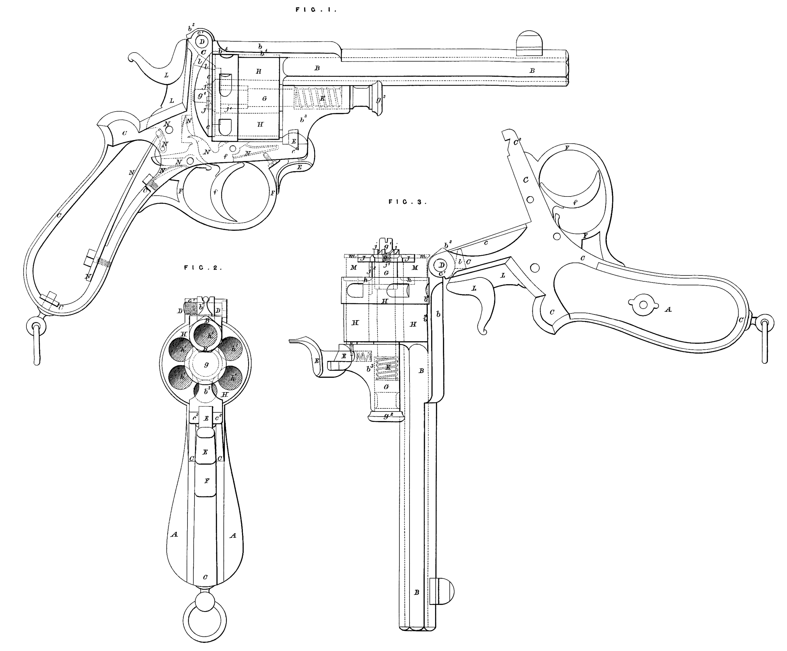
A is the stock, butt, or handle of the pistol; B is the barrel; by strap or band formed of a piece with the barrel; b\ the hinge joint of the strap or band; b’\ portion of the hinge joint which throws back the hammer to the half or safety bent; 63, extension or enlargement of the barrel in front of the cylinder; b*, groove in the strap or band for maintaining the cylinder in position; C is the body of the revolver or pistol; c, the recoil surface of the body; c\ the hinge joint of the body; c2y front end of the pistol body prepared to receive the spring latch E; D is the screw pin which forms the gudgeon of the hinge bl and cl; E is the spring latch with its spiral spring and set screw; E is the trigger guard; /, the trigger; /■, the trigger spring; G is the pin or axis upon which the cylinder rotates, and to the forward end of which the extractor is attached; g, the screw thread formed upon the end of the pin or axis; gx} the screwed cap with solid end, which serves to retain the extractor in position upon the pin or axis; g2} the enlarged end or head of the pin or axis; H is the cylinder; h, the circular sinking in the rear face of the cylinder to receive the extractor; h\ chambers of the cylinder; J is the extractor; j, the ratchet upon the outer face of the extractor; j\ tube of the extractor, through which passes the pin or axis G, and upon which pin or axis the extractor rotates in connection with the cylinder H; f, small pin or guide of the extractor; K, the spiral spring upon the pin or axis G; L, the hammer; l, the beak of the hammer; M, the cartridge; m, the rim or shoulder of the cartridge; N, the mechanism of the lock.
The three Drawings illustrate on an actual scale one mode of putting into operation these improvements, but it will be readily understood that the several parts may be varied, either in form or dimension, to adapt these improvements to revolving pistols of any calibre.
Figure 1 is a side view; Figure 2, a front end view, looking from the muzzle; and Figure 3, a side view with the barrel and attached parts turned upon the hinge after the release of the spring catch, and shewing the extractor as it would appear when disengaged from its position in the cylinder for the extraction and rejection of the expended cartridge cases.
This Invention is not confined to the exact details as herein set forth and illustrated by the accompanying Drawings, as it is sometimes preferred to employ a double mainspring in lieu of a single one, as herein delineated, and sometimes also it is preferred to form the entire mechanism of the lock upon a web or thin plate of metal, which may or may not form part of the body of the pistol, as may be most convenient.
The sheath or holster which is employed facilitates materially when on horseback, or for cavalry purposes, the movements connected with opening the revolver, removing the expended cartridge cases, and recharging, the whole of which operations can thus readily be performed with one hand, leaving the other free for the management of the reins, and this sheath or holster can be attached to the saddle, to a belt, or carried in any convenient manner.
Having thus described and ascertained the nature of the said Invention, and the manner in which it is to be performed, I would observe in conclusion that it is not limited to the precise details herein-before described and illustrated in the annexed Drawings, as the same may be varied without departing from the essential features of the said Invention, neither do I claim the whole of the parts wrhen taken separately and independently of each other, but what I consider novel and original, and therefore claim as constituting the Invention secured to me by the said herein-before in part recited Letters Patent arc,—
First. The said improvements, parts, and mechanism when combined, substantially in the manner lierein-before described and illustrated in the accompanying Drawings.
And, secondly. The arrangements and combinations of parts and mechanism herein-before described, as and for the purposes aforesaid, or any mere modifications thereof.
In witness whereof, I, the said John Piddington, have hereunto set my hand and seal, this Twenty-seventh day of January, in the year of our Lord One thousand eight hundred and seventy-one.
JOHN PIDDINGTON. (l.s.)