
US 115483
UNITED STATES PATENT OFFICE.
BENJAMIN F. JOSLYN, OF NEW YORK, N.Y., ASSIGNOR TO TOMES, MELVAIN & CO., OF SAME PLACE.
IMPROVEMENT IN REVOLVING FIRE-ARMS.
Specification forming part of Letters Patent No. 115,483, dated May 30, 1871.
To all whom it may concern:
Be it known that I, Benjamin Franklin Joslyn, of New York, county of New York, State of New York, have invented Improvements in Revolving Fire-Arms, of which the following is a specification.
My invention consists of certain improvements, too fully described hereinafter to need preliminary explanation, in revolving fire arms, the main objects of the said improvements being to prevent the binding of the cylinder owing to the swelling of the exploded cartridge-cases, to prevent the escape of gases between the said cylinder and the barrel, to enable the exploded cartridge-cases to be readily ejected from the cylinder, and to produce a fire-arm of economical construction.
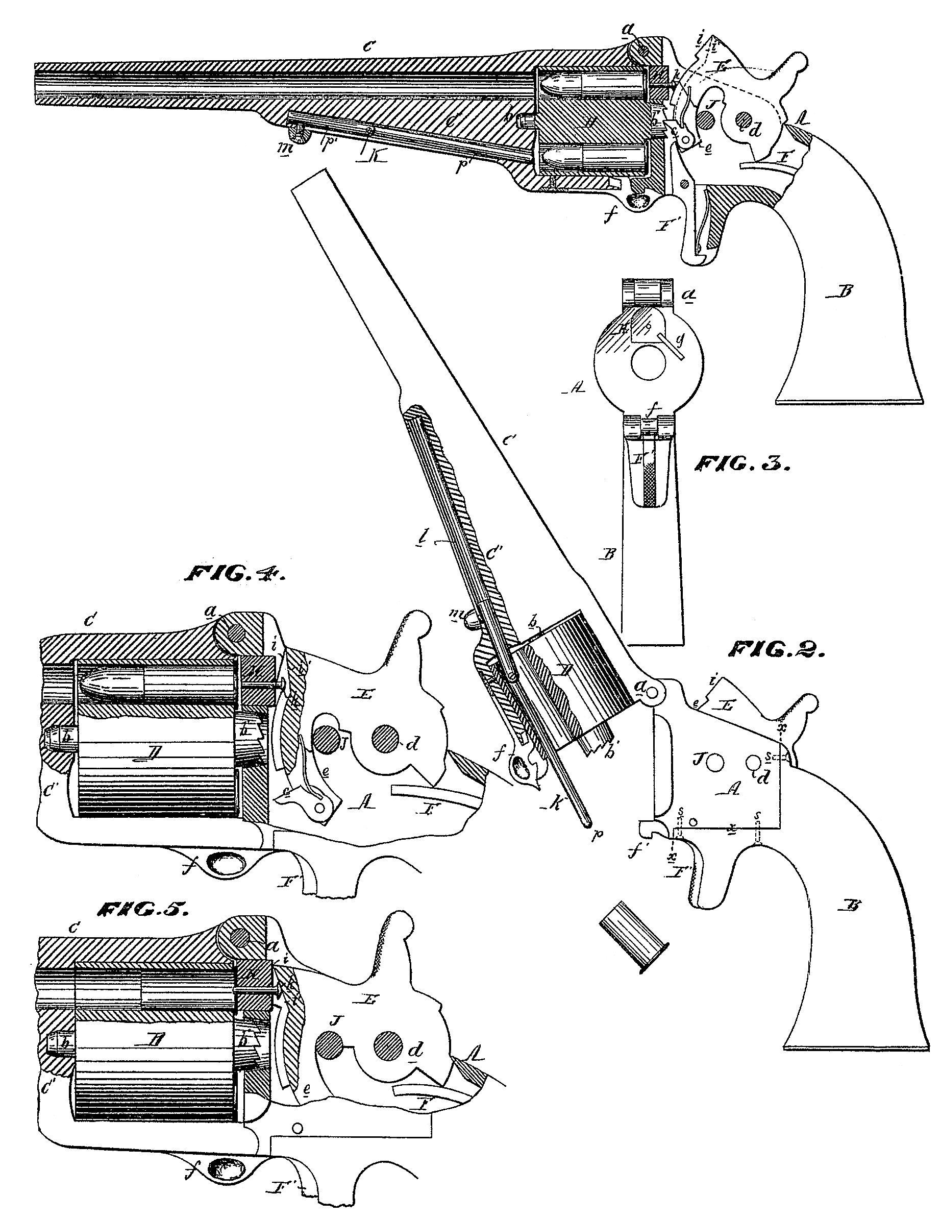
In the accompanying drawings, Figure 1 is a longitudinal section of my improved revolving fire-arm; Fig. 2, a side view of the same, partly in section, showing the hinged barrel thrown up so as to expose the end of the cylinder; Fig. 3, an end view of the frame and stock with the barrel and cylinder detached; and Figs. 4 an 5, enlarged sectional views, in different positions, of portions of Fig. 1.
A represents the frame of the fire-arm, recessed for the reception of the hammer and lock; B, the stock or handle; C, the barrel, hinged at its rear upper end to the frame at the point as and D, the revolving cylinder, adapted to a recess formed for its reception at the rear of the barrel, and having at its front end a pivot, b, turning in an opening formed in the enlargement C’ beneath the barrel, and at its rear end a notched cylindrical projection, b’, adapted to an opening in the frame A and operated, as usual, by a spring tongue or finger, c, attached to the hammer E in such a manner as to bring the chambers of the cylinder successively opposite the barrel on the cocking of the hammer. The latter is hung to the frame A by a pin, d, is acted on by a main Spring, IF, arranged within the stock or handle, and is controlled by a trigger, F’, hung to the frame, and adapted to notches on the edge of a segmental projection, e, of the hammer.
Owing to the method of hinging the barrel to the frame, it can be thrown upward, as shown in Fig. 2, for the purpose of removing the cylinder or of obtaining access to the chambers in the same. The barrel, when lowered as shown in Fig. 1, is locked to the frame by a hooked spring-catch, f, adapted to a fixed hook, f’, on the said frame.
In ordinary revolving fire-arms there is a considerable escape of gas at the joint between the cylinder and the barrel on every discharge of the piece, and as the cylinder has to be fitted closely against the barrel and frame, in order to prevent as far as possible this leakage of gas, the cylinder frequently binds or becomes jammed in its place, owing to the swelling of the heads of the exploded cartridge-cases.
I have overcome both of these objections by the use of a movable or sliding breech-piece, H, Figs. 4 and 5, adapted to a recess in the frame immediately at the rear of the barrel or at the rear of the uppermost chamber of the cylinder, on line with the barrel. The cylinder has a slight longitudinal play, so that it may be turned freely and without binding, owing to the swelling of the heads of the cartridges, and leakage of gas between the said cylinder and the barrel is prevented by means of the movable breech-piece, which, before every discharge is forced forward against the head of the cartridge which is to be struck, this having the effect of moving the cylinder forward and holding it against the barrel. The sliding breech is forced forward by an inclined projection, i, of the hammer on the descent of the latter, and is moved back when the hammer is raised, so as to permit the cylinder to be freely turned by a spring, g, Fig. 3, secured to the frame A and bearing against the face of the said breech-piece. A firing-pin, k, is adapted to and slides in the movable breech, and is also forced forward after the movement of the said breech by an incline, i, of the hammer, as will be hereinafter described. The breech-piece, when moved forward against the cylinder and head of the cartridge, is held with perfect Solidity by the hammer, which descends upon a fixed pin, J, of the frame, this pin holding the hammer rigidly and taking up the force of the recoil, which would otherwise be exerted upon the pivot-pin d. The breech-piece is purposely extended upward to a somewhat higher point than would be required to cover the head of the cartridge, in order that the hammer may be forced downward directly upon the pin J by the recoil.
For the purpose of ejecting the exploded cartridge-cases from the barrel I use a jointed sliding rod, K, adapted to a slotted opening, l, formed in the enlargement C’ beneath the barrel, and operated by a knob or button, m, as will be more particularly described hereinafter.
In using the fire-arm the hammer is first raised to the position of half-cock, in order to enable the breech-piece to be forced back by its spring g and the cylinder to be turned, when, if the latter is to be charged, the spring-catch f is pulled downward to disengage it from the hook.f., and thus unlock the barrel and enable the latter, with the cylinder, to be turned out ward from the frame A, as shown in Fig. 2. After charging the chambers of the cylinder with metallic cartridges, the barrel is lowered and again locked by means of the spring catch f.
To discharge the piece the hammer is brought to the position of full-cock and released by means of the trigger. The inclined projection of the hammer will first strike the rear end of the sliding breech-piece, as shown in Fig. 4 and as the hammer continues to descend the breech-piece will be forced forward by the said inclined projection until the cylinder is held closely against the rear of the barrel, and the said breech-piece is in close contact with the head of the cartridge. All this occurs, how ever, it should be borne in mind, before the firing-pin is caused to strike the cartridge, the said pin being forced forward by the incline i’ of the hammer during the last portion of the downward movement of the latter, and after the breech-piece has been moved forward and is firmly held, so that no premature discharge can take place. The breech-piece cannot possibly yield to the force of the recoil, owing to the arrangement before described of the hammer and pin J. After each discharge the breech-piece will be forced back by its spring into the frame A on the cocking of the hammer, so as to offer no obstruction to the revolving of the cylinder, and after all the cartridges have been discharged the barrel is again unlocked and raised, as shown in Fig. 2, in order to permit the ejectment of the cases by the rod K. The latter consists of two sections, b and b’, the former of which is hinged or swiveled to the latter, so as to enable it to adapt itself to the necessary change of angle in passing through the chambers of the cylinder. The exploded cases are removed one at a time by this jointed rod, in a manner which will be readily understood on referring to Fig. 2, and after all have been ejected the rod is drawn back into its recess l, the cylinder again charged, and the barrel lowered and locked, when the piece will be again ready for use.
The frame A is forged in one piece, as is also the metal portion of the stock or handle B, and these parts are joined together on the lines x x, Fig. 2, and fastened by screws s, so that they can be readily detached. This I have found to be a ready and economical method of constructing this portion of the fire-arm.
I claim—
1. The combination, with the cylinder of a revolving fire-arm, of a sliding breech-piece, H, operating substantially as and for the purposes specified.
2. The said movable breech-piece, operated in one direction by a projection or projections, i, on the face of the hammer on the descent of the latter, and in the opposite direction by a spring, g, or its equivalent, when the said hammer is raised, all substantially as described.
3. The combination, substantially as herein described, of the said movable breech-piece, the hammer, and a fixed pin, J, of the frame of the fire-arm.
4. The firing-pink, adapted to an opening in the movable breech, and so combined with the latter and the hammer that it shall be thrust forward by an incline, i, on the latter after the completion of the forward movement of the said breech-piece.
5. The ejecting-rod X, consisting of two sections, p and p’, hinged or swiveled together, and arranged to be operated substantially in the manner described.
In testimony whereof I have signed my name to this specification in the presence of two subscribing witnesses.
B. F. JOSLYN.
Witnesses:
George W. Hore,
Frank Bottomly.