
US 42379
UNITED STATES PATENT OFFICE.
B. F. JOSLYN, OF STONINGTON, CONNECTICUT.
IMPROVEMENT IN REVOLVING FIRE-ARMS.
Specification forming part of Letters Patent No. 42,379, dated April 19, 1864.
To all whom it may concern:
Be it known that I, B. F. Joslyn, of Stonington, Connecticut, have invented certain Improvements in Revolving Fire-Arms; and I do hereby declare the following to be a full, clear, and exact description of the same, reference being had to the accompanying drawings, and to the letters of reference marked thereon.
My invention relates to improvements in revolvers having cylinders made of two parts, one fitting into the other, my improvements, which are fully described hereinafter, having been made with the view of preventing the accumulation of dirt between the two parts of the cylinder, also with the view of readily loading the cylinder and removing therefrom the spent cartridges.
In order to enable others skilled in the art to make and use my invention, I will now proceed to describe its construction and operation.
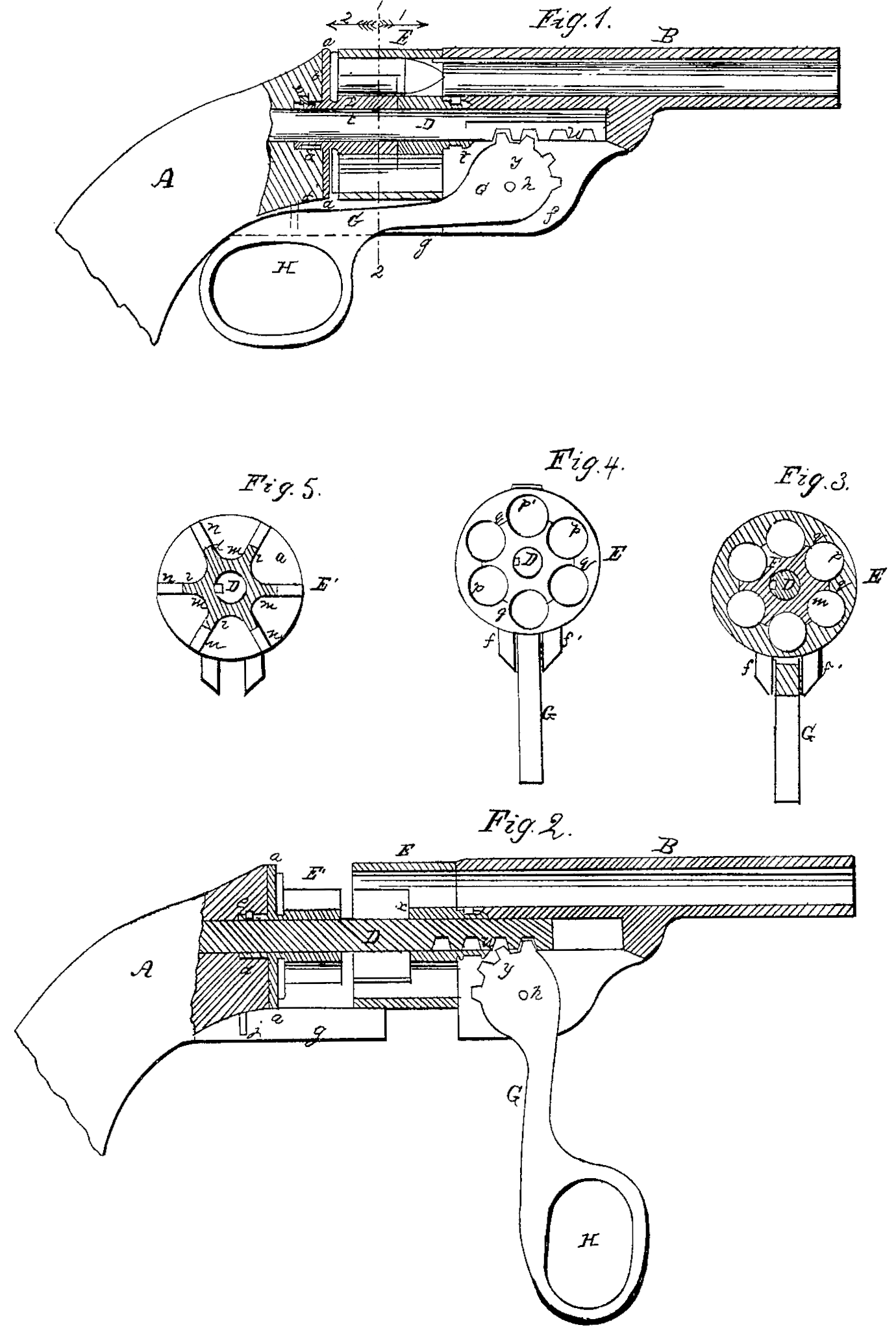
On reference to the accompanying drawings, which form apart of this specification, Figures 1 and 2 are longitudinal sections of my improved revolving fire-arm; Fig. 3, a transverse section on the line 12 of Fig. 1, looking in the direction of the arrow 1; Fig. 4, a section of part of the cylinder; Fig. 5, also a section, on the line 12, of the rear portion of the cylinder, looking in the direction of the arrow 2.
Similar letters refer to similar parts through out the several views.
A is the stock, and B the barrel, of the fire-arm, D being the breech-pin, which is permanently secured to the stock by any suitable fastening.
The main peculiarity of my improved fire-arm is the mode of constructing the cylinder, Which consists of two distinct parts— namely, the exterior portion, E, and the inner or rear portion, E’, the two, when fitted together, constituting a cylinder having in the present instance six chambers.
The rear portion, E’, of the cylinder consists of the circular plate a, at the rear of which is a tubular projection, d, surrounding and fitting snugly to but so as to turn freely on, the breech-pin D, the projection being also arranged to turn freely in the stock, to which it is so confined by a key, e, that the plate a always bears against the end b of the stock. In front of this plate a is another projection, which surrounds and fits snugly to the breech-pin, and which penetrates about half-way through the portion E of the cylinder. This projection, the form of which will be best observed on reference to Fig. 5, consists of six ribs, i i, with concave recesses m m between the ribs. In front of the plate a are also six radial projections, n n, the object of which will be rendered apparent hereinafter.
It will be seen that the portion E is recessed for the reception of the above-described projection on the plate a of the portion E’ of the cylinder, the recessed portion, when the two parts of the cylinder are detached from each other, consisting of a hollow cylinder, Fig. 4, with six ribs, q, and between these ribs concave recesses p.
When the two portions of the cylinder are fitted together, as seen in Fig. 3, the ribs i of the portion E’ coincide with the internal ribs, q, of the portion E, and each concave recess m of the portion ‘E forms, with one of the concave recesses p of the portion E, a circular chamber for the reception of all ordinary metallic cartridge.
It will be seen on reference to Figs. 1, 2 that the above-described projection in front of the plate a penetrates the portion E of the cylinder as far only as the point x, from which point to the front end of the cylinder the chambers are cut through solid metal, as in the cylinders of ordinary revolvers.
The front end of the cylinder has a tubular projection, t, embracing the breech-pin D, and fitting snugly but so as to turn freely in a recess formed in the rear end of the barrel, beneath the bore of the same, a key, v, tending to maintain this projection, with the portion E of the cylinder, in its proper longitudinal position and in contact with the barrel. The breech-pin D is carried forward so as to penetrate a considerable distance into a recess in a projection formed beneath the barrel, and teeth w are formed on the under side of the pin, these teeth being adapted to teeth on the segment y, which forms the small arm of the lever G. The latter has its fulcrum on a pin, h, which passes through two flanges, f and f’, formed beneath the barrel, and between similar flanges, g, beneath the stock. An eye, H, is formed at the end of the lever for facility of handling the same, the eye at the same time serving as an appropriate trigger-guard.
As the lock, trigger, hammer, and devices connected therewith for rotating the cylinder may be similar to those of other revolving fire-arms, and as any one skilled in this class of mechanism can readily apply these parts to my improvement, it has not been deemed necessary to illustrate and describe them.
Operation: As seen in Fig. 1, the several parts of the fire-arm are in a proper position preparatory to the discharge of the load. When the fire-arm has to be loaded the lever G is depressed to the position shown in Fig. 2, in doing which the teeth on the short arm of the lever act on those of the breech-pin, and consequently the barrel is projected outward from the stock, carrying with it the portion E of the cylinder and leaving the portion E’ of the same still in contact with the stock. The weapon is then held vertically, muzzle upward, and the metallic cartridges are arranged on the exposed portion E’ of the cylinder, the heads of the cartridges resting on the plate a and the bodies fitting the concave recesses m. After the cartridges have been thus properly arranged the lever G is restored to its former position, in doing which the portion E of the cylinder slides over the projecting part of the portion E’ and over the metallic cartridges. When a proper junction of the two portions of the cylinder is effected by the movement of the lever each cartridge is contained in a separate chamber, and the two parts of the cylinder are in effect the same as a cylinder of the ordinary construction.
It will be seen that the head of each cartridge is isolated from that of the adjacent cartridges by the radial ribs n, Fig. 5, that the case of the cartridge covers all the joints of the two portions of the cylinder, and consequently that no dirt can accumulate between and impair the efficiency of these joints.
When the spent cartridges have to be with drawn the lever G is again depressed, and the portion E of the cylinder consequently moved away from the portion E’, to which the cases of the cartridges adhere, as their heads fit in recesses formed in tine said portion E’, as seen in Fig. 1. After the piece E has been moved forward to a proper distance the cartridge-cases will fall from the piece E, and new cartridges may be introduced into the cylinder in the manner described above.
In loading the fire-arm there is no necessity for detaching the cylinder entirely, as in other breech-loading revolvers, one movement of the lever being all that is necessary to arrange the cylinder for receiving the cartridges, and another movement all that is necessary for adjusting the cylinder and its charges preparatory to firing.
I wish it to be understood that I do not desire to claim broadly a cylinder composed of two pieces, one fitting into the other, one portion of each chamber being formed in one piece and the other portion of each chamber in the other piece, as described above; but
I claim as my invention and desire to secure by Letters Patent—
1. Making that portion of the piece E’ which penetrates the portion E shorter than the case of the cartridge, so as to prevent the accumulation of dirt between the two parts of the cylinder, as set forth.
2. The piece E’, with the plate a and radial ribs n, and recesses for the reception of the heads of the cartridges, the whole being constructed substantially as and for the purpose set forth.
In testimony whereof I have signed my name to this specification in the presence of two subscribing witnesses.
B. F. JOSLYN.
Witnesses:
N. B. Palmer, 2d,
O. B. Grant.