
US 142376
UNITED STATES PATENT OFFICE.
IMPROVEMENT IN REVOLVING FIRE-ARMS.
BENJAMIN K. DORWART, OF ROCKLAND, ASSIGNOR TO HIMSELF AND IRA C. WINSOR, OF COVENTRY, RHODE ISLAND.
Specification forming part of Letters Patent No. 142,376, dated September 2, 1873; application filed July 5, 1873.
To all whom it may concern:
Be it known that I, Benjamin K. Dorwart, of Rockland, in the county of Providence and State of Rhode Island, have invented a new and Improved Revolving Fire-Arm, of which the following is a specification:
The invention consists in the improvement of fire-arms, as hereinafter described and claimed.
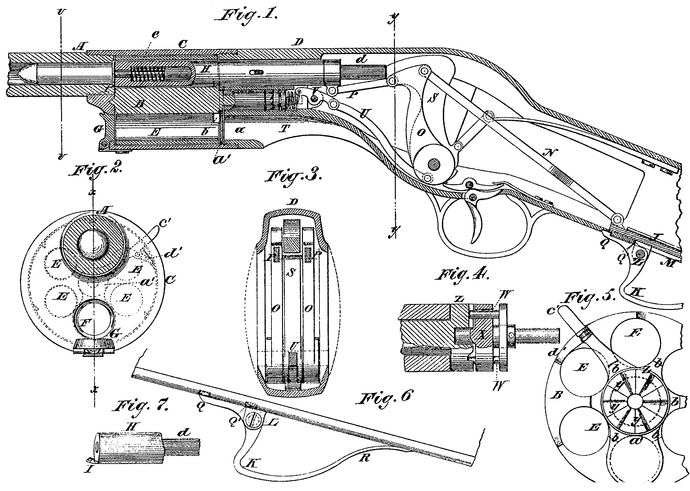
Figure 1 is a longitudinal sectional elevation of my improved revolving fire-arm taken on the line x x of Fig. 2. Fig. 2 is a trans verse section taken on the line v v, Fig. 1. Fig. 3 is a cross-section taken on the line y y, Fig. 1. Fig. 4 is a section of the ratchet-clutch mechanism for turning the revolving chamber-cylinder. Fig. 5 is an end elevation Fig. 6 is a side elevation of a portion of the stock and the slide for Working the pusher and cocking the hammer; and Fig. 7 is a detail of a portion of the pusher and the firing-pins, which work in the pusher, which is made hollow for the purpose.
Similar letters of reference indicate corresponding parts.
A is the barrel; B, the revolving chamber cylinder; C, a case inclosing the cylinder; D, the stock. E represents the chambers of the cylinder, and F the opening through the front end of the inclosing-case, through which the cartridges are introduced. Said opening is closed by a cap, G, which is held either in the open or closed position by a spring joint. The cartridges are, by the rotation of the chamber-cylinder, carried in front of the pusher H, which is in line with the bore of the barrel, the flanges being engaged by a catch, I. The pusher slides forward and pushes the cartridges out of the chambers into the barrel, as represented in Fig.1 to be exploded therein. It is moved forward by the slide J in the hollow breech behind the hammer, which is worked by the bar K, pivoted to it at L by an ear projecting out through a slot, M, in the stock. This slide is connected to the pusher by the bars N, rock-levers O, and link P. The bar K has a catch, Q, which springs into a notch in the stock by the action of the part R, which is a spring, and locks the pusher in the forward position to sustain the recoil. When the pusher is to be withdrawn the catch Q is disengaged from the notch by the force applied to the front part of bar K to pull it back, which forces it out by springing said bar at R. The rock-arms O carry the firing-hammer S back and cock it. By pulling back this guard-spring K a trifle past the cocking-point it again locks behind the ledge Q’, and holds the pusher back while the revolving chamber is being filled. The back movement of the rock-arms O forces the spring T around in the direction to revolve the cylinder by means of the link U and the lever V, but the pusher prevents it from turning while it remains in the cylinder; but, as soon as it escapes at the end, the spring throws the cylinder forward by the clutch-pins W, of which there are two in the part X. of the clutch, engaging the notches Y in the part Z of the clutch. There are as many notches as there are chambers. The forward movement of the rock-arms returns the spring and the clutch-pins to the position for turn of the pusher. When the pusher withdraws from the chamber it draws the expended shell into it, and the shell is retained in the cylinder until it comes around to the opening F, when it is expelled through the passage a by the next cartridge put in. The said passage is provided with a gate, a’, for closing it to retain the cartridges. It is pivoted on the axis of the cylinder, and has a handle, c’, projecting out at one side of the cylinder to be operated, and to this handle a pawl, d’, is attached to engage the cylinder B in suitable notches provided for it, and turns the cylinder when it is to be recharged. The cylinder is notched at b to revolve past the projecting catch I of the pusher. The firing-rod cl is arranged inside of the pusher, which is made hollow for the purpose, and has a spring, c, to throw it back.
It will be seen that, by pulling the slide J back and pushing it forward, the cartridge shell will be withdrawn from the barrel, the hammer will be cocked, the cylinder revolved; and another cartridge introduced into the barrel ready for firing.
Having thus described my invention,I claim as new and desire to secure by Letters Patent—
1. The bar K, slide J, bars N, rock-levers O, and link P, constructed and relatively arranged as described, to operate the pusher.
2. The oscillating lever W that actuates clutch-spring connected through links and swinging arms O to the pusher-operating mechanism, substantially as specified.
3. The gate a’, handle C, and ratchet mechanism combined with the cylinder, in the manner and for the purpose described.
BENJ. K. DORWART.
Witnesses
John Winsor,
James B. Capwell.