
US 39405
UNITED STATES PATENT OFFICE.
BENJAMIN F. JOSLYN, OF STONINGTON, CONNECTICUT.
IMPROVEMENT IN REVOLVING FIRE-ARMS.
specification forming part of Letters Patent No. 39,405, dated August 4, 1863; antedated May 26, 1863.
To all whom it may concern:
Be it known that I, Benjamin F. Joslyn, of Stonington, New London county, Connecticut, have invented certain Improvements in Breech-Loading Revolving Fire-Arms; and I do hereby declare the following to be a full, clear, and exact description of the same, reference being had to the accompanying drawings, and to the letters of reference marked thereon.
My invention relates to improvements in that class of revolving fire-arms in which metallic cartridges are used; and my improvements consist, first, of a device for preventing the spent cartridges from interfering with the free rotation of the cylinder; secondly, of a novel device for operating the cylinder through the movement of the hammer; thirdly, of a device serving the double purpose of a center-pin for the front of the cylinder and a suitable instrument for removing the spent cartridges from the chambers of the cylinder.
In order to enable others skilled in the art to make and use my invention, I will now proceed to describe its construction and operation.
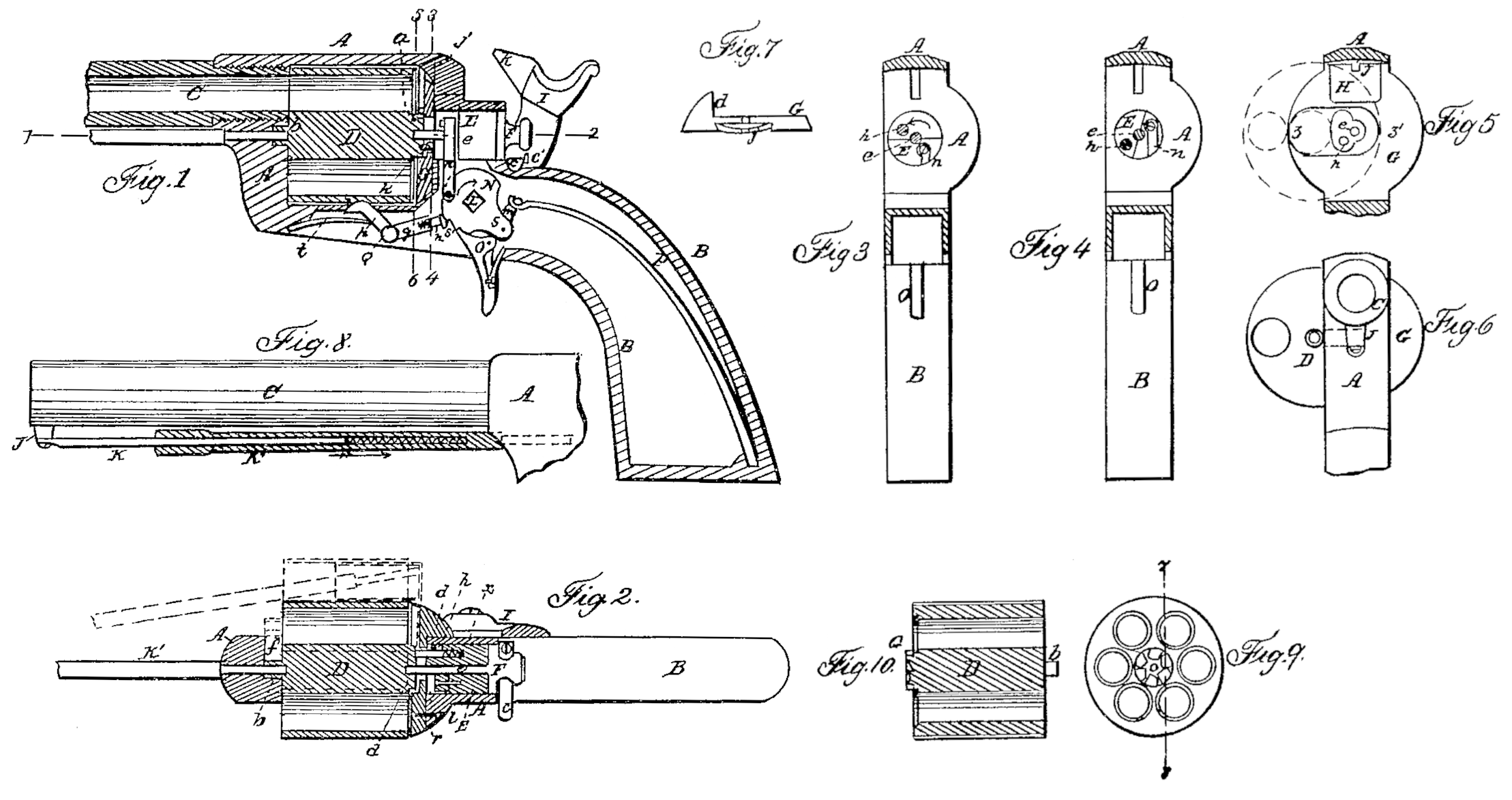
On reference to the accompanying drawings, which form a part of this specification, Figure. 1 is a longitudinal section of my improved breech-loading revolving fire-arm; Fig. 2, a sectional plan on the line 12, Fig. 1; Figs. 3 and 4 transverse sections on the line 3 4, Fig., 1; Fig. 5, a transverse section on line 5 6, Fig. 1; Fig. 6, an end view; Figs, 7 and S, detached views of parts of the fire-arm; Fig. 9, a view of the rear of the cylinder; and Fig. 10 a longitudinal section of the same on the line 7 8, Fig. 9.
Similar letters refer to similar parts through out the several views.
A is the frame of the pistol, an extension, B, from the rear of which forms the stock or handle, the barrel C being secured to the front end of the frame in the usual manner.
In the rectangular opening of the frame. A revolves the cylinder D, at the rear of which is a projection, a, having as many depressions as there are chambers in the cylinder, each depression being inclined on one side and abrupt on the other, as best observed on reference to the sectional view, Fig. 9.
On the front end of the cylinder D is a tubular projection, b, which is arranged to fit snugly in, and, when necessary, to slide to and fro in a groove, f, formed in the frame A. (See Fig. 2.)
In the frame, at the rear of the cylinder, is a circular opening in which the cylindrical block E fits snugly, and through this block passes a pin, e, the end of which fits into a recess in the projection a of the cylinder, a portion of the head F of the pin fitting in the opening of the frame which contains the block, in which position the head is retained by the spring C, the latter having a lip, c’, the purpose of which will appear hereinafter.
It will be observed; on reference to Figs. 2, 3, and, 4 that a portion of the front end of the block E is cut away, leaving a semi-cylindrical projection, in which is a longitudinal opening of for the reception of the pin h, the outer end of which is so beveled as to engage properly in the depressions of the projection a, a spiral spring in the opening and at the rear of the pin tending to force the latter toward the cylinder, while the pin is retained-within proper limits by a projection passing into an oblong slot in the block E, as seen in Fig. 2. It should be understood that this block E is arranged to turn freely in the frame, but to have no longitudinal movement.
Between the rear of the cylinder and the frame intervenes a breech-plate, G, in which is a central opening of such shape and dimensions as to allow for the free movement of the pin e and pin h, the plate having on one side a lug, d, fitting against the side x of the frame, to which the plate is secured by a set screw, e, Fig. 2.
In the face of the plate G is a depression, the edges of which are beveled and adapted to the beveled edges of a recoil-plate, H, which fits loosely in, and so as to be readily withdrawn, vertically from, the plate G when the latter is detached from the frame. This recoil-plate is so situated as to form the rear of one of the chambers of the cylinder when the front of the chamber coincides with the bore of the barrel, the face of the recoil-plate being slightly convex and projecting beyond the face of the breech-plate, while the inside is concave in Fig. 7. The recoil-plate, being somewhat loose in the recess of the breech-plate, is capable of yielding to a limited extent at the moment the discharge of the cartridge takes place, but instantly recovers its former position after the discharge.
In the upper edge of the recoil-plate is cut a notch, i, through which passes the point k of the hammer I as it falls upon the edge of the flange or enlargement of the metallic cartridges used in connection with my improvements.
On the hammer-pin L is secured a cam-shaped lever, N, having the usual notches, in which engages the upper end of the trigger O, the main-spring P being connected to the arms of this lever by a link, m.
From the face of the lever N projects a pin, to which is connected the lower end of the connecting-rod n, the upper end of the latter being jointed to a pin on that part of the block from which, as before remarked, a portion is cutaway.
To a spindle, Q, attached to the frame below the cylinder,is hinged a lever having two arms, p and q, the latter having an orifice for the reception of the sliding rod r, the head s’ of which is pressed against the edge of the cam-shaped lever N by a spiral spring contained in the said orifice.
A flat spring, t, is secured at one end to the under side of the frame, the other end bearing against the under side of the arm p, the rounded portion of which is arranged to fit in slight depressions formed in the cylinder at such points that when the end of the arm is in one of the said depressions one of the chambers of the cylinder must coincide with the bore of the barrel.
To a projection, J, beneath the barrel, and near the muzzle, one end of a rod, K, is so jointed that it can be moved laterally, the rod fitting snugly, but so as to slide freely, in the tubular rod K’, the rear end of which passes through the frame A and into the tubular projection b of the cylinder, thus forming the pin on which the front end of the said cylinder revolves. A spiral spring contained within the tubular rod K’, and bearing against the rod K, tends to maintain both rods in their proper position when not required for the use explained herein after.
On cocking the hammer the lever N will turn in the direction of its arrow, and through the connecting-rod in cause the cylindrical block E (which, while the hammer was down, occupied the position shown in Fig. 3) to turn in the direction of its arrow. As the lever N turns the friction between its edge and the head of the pin r causes the arm q to be elevated, and the arm p to be consequently depressed, free from the depressions in the cylinder, thereby causing the latter to be released. The pin h, owing to the movement imparted to it by the partial turning of the block E, will, as it bears against the abrupt side of one of the depressions in the projection a of the cylinder, move the latter round to an extent sufficient to bring into a line with the bore of the barrel that chamber of the cylinder next to that which had, prior to the movement of the cylinder, coincided with the said bore. When the hammer has been brought to the position of full-cock the arm q is released, and the spring t forces the arm p against the cylinder, the head of the arm entering one of the depressions, so that the cylinder is retained in a proper position prior to the falling of the hammer, and will remain in that position during the descent of the hammer and until the latter is again moved back. On releasing the hammer the lever N is turned by the action of the spring P in the direction contrary to that pointed out by the arrow, the hammer striking the edge of the flange of the cartridge and discharging the contents of the same. During this movement of the lever the block E is turned back to its former position. The pine, sliding over the inclined side of the depression in the projection a of the cylinder, takes its place in the adjacent depression preparatory to a repetition of the above-described movements.
In fire-arms of the class to which my improvements relate the free turning of the cylinder is obstructed to a greater or less degree, owing to explosion of the contents back against the breech-plate, thereby causing an undue friction, which has been the great objection to the use of metallic cartridges in revolving fire-arms. The main object in my present improvements has been to overcome this difficulty.
It should be understood that the heads of the cartridges in the cylinder, prior to their discharge in succession, come in contact, but only just in contact, with the convex face of the recoil-plate H, so that no undue force is required in revolving the cylinder and transferring the heads of the cartridges in succession to a position coinciding with the recoil-plate, as little force is required in my improvements to move the head of a spent cartridge from the recoil-plate, for the following reasons: The moment the discharge takes place the spent cartridge is forced with a violent concussion against the recoil-plate, and the latter yields slightly to the force of the shock. The instant the latter is expended, however, the plate, owing to its elasticity, recovers its former position, pushes back or compresses the head of the cartridge, so that it is either clear of the plate or bears so lightly against the same as to present no obstruction to the free turning of the cylinder.
When the empty cartridge-cases have to be discharged from the chambers preparatory to reloading, the hammer is brought to half-cock, the spring c is depressed below the edge of the head F of the pine, and the latter is withdrawn until arrested by the lip c’ of the spring, which prevents its further outward movement. The tubular rod K is then pushed forward until its end is released from the projection b of the cylinder, as well as from the frame, when, by a lateral movement of the-cylinder, which is now free from the pins on which it had turned, it may be thrown out to the position shown in Figs. 5 and 6, the projection b passing along the groove f of the frame, and the projection a moving in the oblong slot in the breech-plate until it strikes the edge z, Fig. 5, which prevents any further outward movement of the cylinder. The rods K and K’ are then returned to one side and the rod K’ drawn back so that its end may enter one of the chambers of the cylinder and the empty cartridge-case, and be used as an instrument for pushing the latter from the chamber. (See Fig. 2.) After a case has been discharged from one chamber the cylinder is turned by the finger, and thumb until the adjacent chamber, with its empty case, is brought into a position to be treated in a like manner, and after all the cases have been removed the cylinder is reloaded and pushed back to its place, the pine being moved into the orifice of the projection a and the end of the rod K’ into the orifice of the projection b, when the fire-arm is in a condition to be again discharged.
I do not desire to claim broadly the use, in revolving fire-arms, of a breech-plate with a projection against which the head of the metallic cartridge bears when brought to a position to coincide with the bore of the barrel; but
I claim as my invention and desire to secure by Letters Patent—
1. In connection with revolving fire-arms arranged for use of metallic cartridges, a recoil-plate on the frame, or on a breech-plate attached to the frame, said recoil-plate being situated at the rear of the cartridge when the latter is in position. to be discharged, and operating so as to permit the free turning of the cylinder, as herein described.
2. The block E, arranged to turn in the frame on the movement of the hammer, and having a yielding pin, h, adapted to the recesses in the rear of the cylinder, the whole being arranged and operating substantially as and for the purpose herein set forth.
3. The rod K and tubular rod K’, with its spring, the whole being connected to the barrel, substantially as described, and arranged to serve the double purpose of a front center-pin for the cylinder and an instrument for discharging the spent cartridges.
In testimony whereof I have signed my name to this specification in the presence of two subscribing witnesses.
B. F. JOSLYN.
Witnesses:
James H. Parsons,
Jackson Harrington.