
US 469465
UNITED STATES PATENT OFFICE.
CARL J. EHBETS, OF HARTFORD, CONNECTICUT, ASSIGNOR TO THE COLT’S
PATENT FIRE ARMS MANUFACTURING COMPANY, OF SAME PLACE.
SAFETY-LOCK. FOR REVOLVERS.
SPECIFICATION forming part of Letters Patent No. 469,465, dated February 23, 1892.
Application filed November 2, 1891, Serial No. 410,596. (No model.)
To all whom it may concern:
Be it known that I, CARL J. EHBETS, of Hartford, in the county of Hartford and State of Connecticut, have invented a new Improvement in Revolvers; and I do hereby declare the following, when taken in connection with accompanying drawings and the letters of reference marked thereon, to be a full, clear, and exact description of the same, and which said drawings constitute part of this specification, and represent, in—
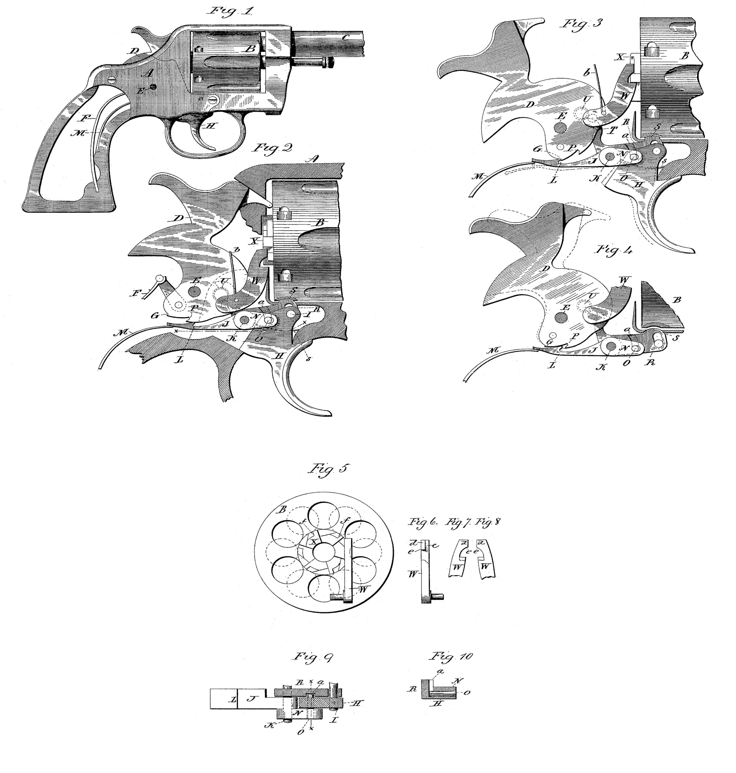
Figure 1, a side view of the revolver complete, the stock on one side removed; Fig. 2, a longitudinal section of the frame, showing the mechanism in side view, the parts in the normal position; Fig. 3, the same as Fig. 2, showing the parts in the position of the hammer at full cock; Fig. 4, the same as Fig. 3, illustrating the operation of the releasing hammer and trigger at the same time; Fig. 5, a rear end view of the cylinder, showing the hand in the up position or position when the hammer is cocked; Fig. 6, a face view of the hand; Fig. 7, a side view of the hand looking from the outside or right of Fig. 5; Fig. 8, a side view of the hand looking from the inside; Fig. 9, a plan view of the trigger, sear, and bolt; Fig. 10, a transverse section cutting on line x x of Fig. 9.
This invention relates to an improvement in revolvers, having special reference to that class of revolvers in which the hammer is cocked by hand in contradistinction to being self-cocking and such as are commonly called “single-acting” revolvers. In this class of revolvers after the hammer has been brought to full-cock and caught by the sear if it be desirable to drop the hammer without discharge the operator places his thumb upon the hammer to retard its descent and at the same time pulls the trigger; but it not infrequently happens that the hammer escapes from the thumb, and, flying forward, strikes a cartridge in the cylinder and produces accidental explosion. Again, when the hammer stands at full-cock an accidental quick pull, like a blow upon the trigger, will release the hammer and may produce explosion, because, although the hammer would naturally be caught by the sear at the half-cock notch, this part of the sear, as well as that of the hammer, is necessarily delicate and liable to break under the blow of the falling hammer.
The object of my invention is to overcome these difficulties; and it consists in the construction and combination of mechanism, as more fully hereinafter described, and particularly recited in the claims.
A represents the frame or receiver, B the cylinder, and C the barrel, all of common and well-known construction.
D represents the hammer, which is hung upon a pivot E in the frame in the usual manner and is provided with the usual mainspring F, and on the under side of the hub is the usual full-cock notch G.
H represents the trigger, which is hung in the frame below the cylinder upon a pivot and so as to swing in a plane parallel with the plane of the hammer. In rear of the trigger the sear J is hung upon a pivot K, so as to swing in the same plane as the trigger. The sear extends rearward and is constructed with a shoulder L, which is adapted to engage the hammer at full-cock, as represented in Fig. 3. A spring M is provided, which bears upward upon the under side of the rear end of the sear, so as to press it upward toward the hammer and so as to force the sear into engagement with the notch of the hammer when brought to full-cock. The sear forward of the hub is constructed with an arm M, which is hung to the trigger upon a pivot O in rear of the pivot I, on which the trigger is hung, the connection between the arm N and the pivot O being slotted, so as to allow the swinging movement of both the trigger and the sear and so that a pull upon the trigger, as indicated in broken lines, Fig. 3, will raise the forward arm of the sear and correspondingly depress the sear at the rear against the sear-spring, and so as to withdraw the sear from the full-cock notch and release the hammer. The sear-spring M operates through the sear upon the trigger, so as to serve both as a sear and trigger spring.
The periphery of the hub of the hammer forward of the full-cock notch G is drawn inward toward the pivot of the hammer to the half-cock notch P, as clearly seen in Fig. 2, and so that the sear, having escaped the full-cock notch and permitted under the action of its spring to ride upon that retreating surface of the hub of the hammer, will rise to the extent of the depression or drawing in of that surface until the half-cock notch is reached in Fig. 4 and so that an upward movement of the sear beyond its normal position will be produced, if permitted, during the first part of the descent of the hammer and before the half-cock notch is reached. Beyond the half-cock notch, however, the periphery of the hub of the hammer is such as to permit the sear to stand in its normal position, as seen in Fig. 2. By this construction, the hammer having been placed at full-cock, as seen in Fig. 3, the operator, when desiring to drop the hammer without a blow, should pull the trigger with his thumb upon the hammer, as, usual in such operation, and should he lose control of the hammer and trigger, as is frequently the case, the sear will be forced by its spring into the path of the half-cock notch, as seen in Fig. 4, so that the half-cock notch will catch upon the shoulder or nose of the sear, as seen in broken lines, Fig. 4, and thereby prevent the hammer from reaching its forward position, so as to impart its blow.
As a further protection against accidental discharge a partial return movement is given to the cylinder in such accidental release of the hammer and trigger.
R represents the usual bolt by which the cylinder is locked. It is hung, as here represented, upon the same pivot K as the sear and so as, to swings up and down and is provided with the usual spring s, the tendency of which is to yieldingly hold the bolt in engagement with one of the notches of the cylinder, the spring yielding for the depression of the bolt, so as to permit the rotation of the cylinder, its nose S being adapted to engage a corresponding notch in the periphery of the cylinder. The bolt is provided with a laterally-elastic tail T, which extends up into the path of a cam-shaped stud, (indicated at U in broken lines, Figs. 1 and 3,) and so that as the hammer is thrown rearward, as in cocking, it will, through, the said arm T, turn the dog downward, so as to clear it from the notch in the cylinder, and so that the cylinder may be revolved by means of the pawl W, which is hung to the hammer and its nose adapted to operate upon a ratchet X on the rear end of the cylinder, as usual. Then when the hammer returns the cam-shaped end of the stud U strikes the arm T, which yields laterally, so that a descent of the hammer has no effect upon the bolt. This is the usual construction and does not require to be illustrated in detail for its clear understanding.
The bolt R is constructed with a groove upon its side next the trigger, as seen in Figs. 3, 9, and 10, and the pivot O, which connects the trigger and sear extends into the groove a, as seen in Figs. 9 and 10. The groove a extends through the upper side of the bolt and so far down upon the side of the bolt that when the trigger is in its normal position, as seen in Fig. 2, the bolt will stand in engagement with the cylinder. So, also, when the hammer stands at full-cock, as in Fig. 3, the bolt will stand in engagement with the cylinder to lock the cylinder in place to properly receive the blow of the hammer upon the head of the cartridge. The pull of the trigger has no effect upon the bolt R, because the pivot O, which connects the trigger with the bolt, will simply rise in the groove a, it working freely therein; but after the hammer escapes from the full-cock notch, as seen in Fig. 3, and if the trigger should be released, the sear is free to strike that portion of the periphery of the hub in rear of the full-cock notch, and that surface being drawn inward or receding, as before described, so as to be concentric to the axis on which the hammer turns, permits the rear end of the sear, under the action of its spring, to rise to a point considerably above the position which it occupies when at full-cock, and such raising of the rear end of the sear under the action of its spring correspondingly depresses the forward end or arm N of the sear, and this depression brings the pivot or stud O, which connects the sear with the bolt R, to bear upon the lower end of the groove a in the bolt, and so as to depress that bolt to a sufficient extent to withdraw it from its notch in the cylinder, as represented in Fig. 4. Consequently under this condition the cylinder is free to rotate; but this freedom of the cylinder can only occur after the hammer has commenced its descent and the trigger has been released, as in the accidental operation before mentioned, for when the trigger is continually held back during the descent of the hammer the pivot I, fixed in the trigger and connecting it with the sear and the latter with the bolt, is raised so as to prevent its action upon the end of the slot a in the bolt. As the hammer flies forward, the hand W is drawn downward over the teeth of the ratchet, and bears thereon under the friction of its spring b, this spring being the usual hand-spring. The cylinder being freed, as before described, in an accidental discharge, and the hand drawing over the teeth of the ratchet in frictional contact therewith will tend to return the cylinder to the extent of the drag of the hand upon the ratchet after the cylinder is released, and thereby take the cartridge which the hammer would have struck had the cylinder remained stationary, so far to one side that the nose of the hammer will strike the cylinder between that cartridge and the next, and thereby prevent possible explosion under the accidental blow of the hammer should it reach its extreme forward or down position.
While the frictional contact between the hand and the ratchet in the usual construction would generally be sufficient to produce the partial return movement of the cylinder above mentioned, it is desirable that the return movement should be made more positive than that simple usual frictional contact. To this end the nose of the hand instead of being inclined downwardly and rearwardly entirely across its face,as in the usual construction, so that it may the more readily escape from the teeth of the ratchet, the nose of the hand is constructed so that a portion c of its face (see Fig. 6) is inclined, while the other portion d is permitted to project, so as to form a shoulder e, (see Figs. 6, 7, and 8,) and the back of the teeth of the ratchet X are constructed with corresponding shoulders f. (See Fig.5.) The shoulders of either the hand or the ratchet, or both, are made abrupt, but yet so that under sufficient force the shoulder of the hand may escape from the shoulder of the ratchet. The inclined portion of the nose of the hand will permit it to strike the back of the tooth next below the one which it engaged in rising and readily escape therefrom, and the abrupt shoulder e of the hand will escape the corresponding shoulder f on that tooth of the ratchet should the cylinder be firmly held; but if the cylinder should be released, as before described, then that abrupt shoulder of the hand engaging the corresponding shoulder on the said tooth of the ratchet will give the hand so firm a hold upon the ratchet that the return movement of the cylinder will be produced corresponding to the movement of the hand after such engagement is made, and this movement should be such as to give to the cylinder substantially half a step backward, as indicated in broken lines, Fig. 5, and so as to bring the space between the chambers of the cylinder into line with the hammer.
The construction and arrangement where by the bolt is withdrawn from its engagement with the cylinder, so as to permit the partial return movement of the cylinder, is desirable as an additional safety device to that which the sear would otherwise possess; but the connection between the bolt and the sear to produce this unlocking of the cylinder may be omitted.
While this invention is specially adapted to single-acting revolvers, it will be evident to those skilled in the art to which this invention pertains that the invention may be applied to automatic or self-cocking revolvers, so that if in letting down the hammer of such revolvers the hammer and trigger should escape the control of the operator the revolver will possess the same means for preventing accidental discharge.
I claim—
1. In a revolver, the hammer constructed upon the periphery of its hub with a surface receding from the point of full-cock notch forward and toward the center of motion of the hammer, and a sear hung upon a pivot below the hammer and forward of said receding surface of the hammer, the rear end of the sear adapted to work upon said receding surface, a spring having a tendency to force the sear toward the hub of the hammer, the sear having an extension or arm forward of its pivot, with a trigger hung forward of the sear and connected to the said arm forward of the sear pivot, substantially as described.
2. In a revolver, the combination of a hammer having the periphery of its hub constructed with a surface receding from the point of full-cock notch and toward the pivot, a sear hung upon a pivot forward of said receding surface of the hammer, the sear extending rearward and adapted to bear upon said receding surface of the hammer, a trigger adapted to engage said sear, and a bolt hung in the receiver and arranged to swing in the same plane as the said sear, the said bolt being adapted to lock the cylinder, and mechanism between the said bolt and sear, substantially as described, and whereby the said sear is adapted to withdraw the bolt from the cylinder as the sear passes onto the said receding surface.
3. In a revolver, the combination of a hammer having the periphery of its hub constructed with a surface receding from the point of full-cock notch and toward the pivot, a sear hung upon a pivot forward of said receding surface of the hammer, the sear extending rearward and adapted to bear upon said receding surface of the hammer, the sear provided with an extension forward of its pivot, a trigger adapted to engage said sear and impart to the sear the releasing movement for the discharge of the hammer, and a bolt hung in the receiver at the side of said extension from the sear, the said bolt adapted to engage and lock the cylinder in the firing position and constructed with a groove upon its side nearest said extension, with a stud projecting from said extension into said groove, the lower end of said groove in the bolt being in such position relatively to the stud on the sear that when the sear is in its normal position the bolt will be free to engage the cylinder, substantially as described.
4. In a revolver, the cylinder provided at its rear end with a ratchet, the said ratchet constructed with shoulders f upon the back of its respective teeth, combined with the hand W, having its nose constructed with a part of its face inclined downward and rearward and the remainder of its face d projecting so as to form an abrupt shoulder e, the said shoulder being adapted to engage the said shoulder f on the teeth of the ratchet, with mechanism, substantially such as described, to release the cylinder as the hand descends, substantially as and for the purpose described.
In testimony whereof I have signed this specification in the presence of two subscribing witnesses.
CARL J. EHBETS.
Witnesses:
JAS. S. BRYANT,
A. LT. ULRICH.