
US 303135
UNITED STATES PATENT OFFICE.
CARL J. EHBETS, OF HARTFORD, CONNECTICUT, ASSIGNOR TO COLTS PATENT FIRE ARMS MANUFACTURING COMPANY, OF SAME PLACE.
REVOLVER.
SPECIFICATION forming part of Letters Patent No. 303,135, dated August 5, 1884.
Application filed May 21, 1884. (No model.)
To all whom it may concern:
Be it known that I, CARL J. EHBETS, of Hartford, in the county of Hartford and State of Connecticut, have invented new Improvements in Revolvers; and I do hereby declare the following, when taken in connection with accompanying drawings and the letters of reference marked thereon, to be a full, clear, and exact description of the same, and which said drawings constitute part of this specification, and represent, in–
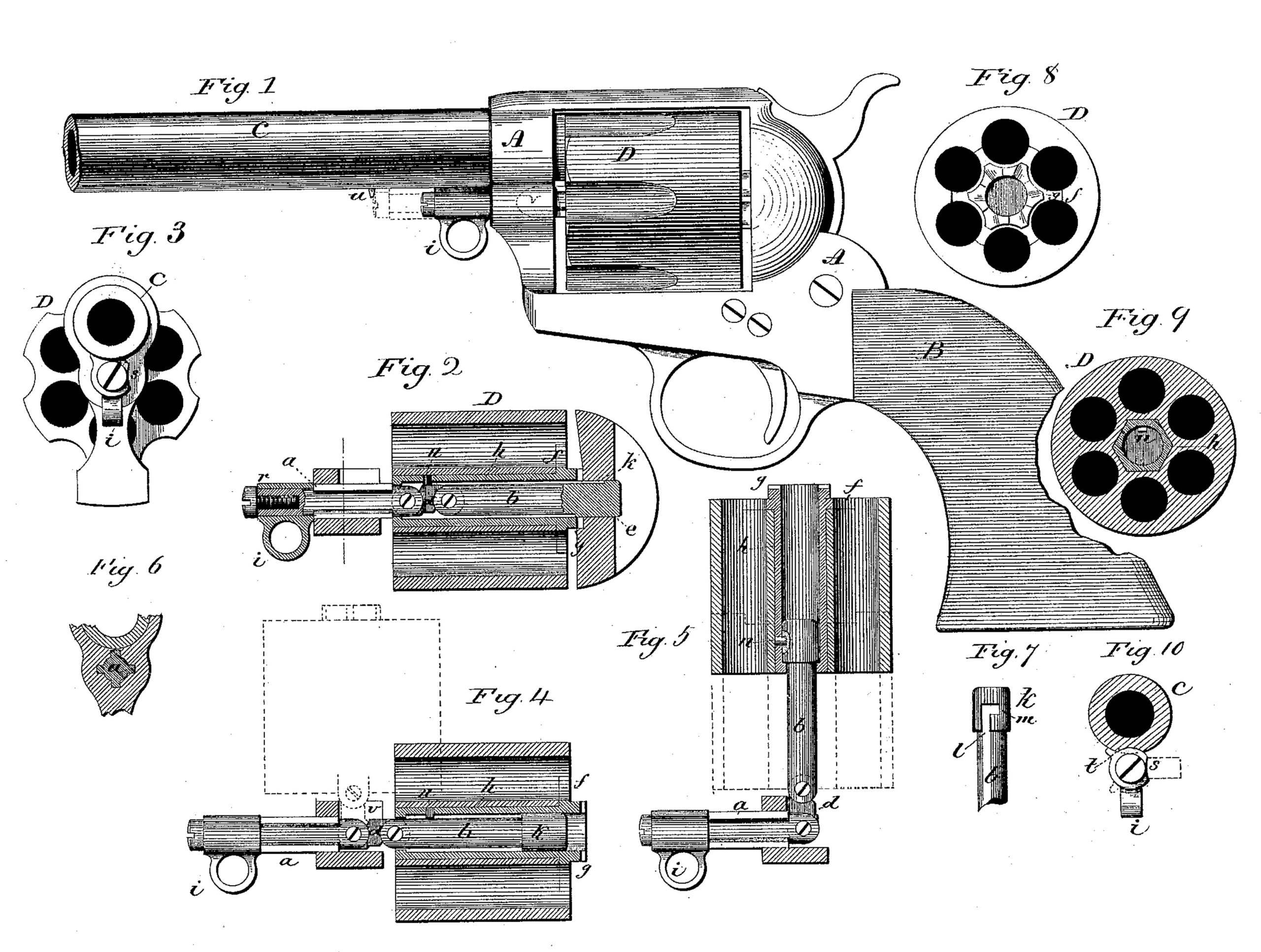
Figure 1, a side view; Fig. 2, a horizontal section; Fig. 3, a front end view; Figs. 4, 5, 6, 7, 8, 9, and 10, detached views to illustrate the construction and operation of the improvement.
This invention relates to an improvement in revolvers, with special reference to the revolver known as “Colts’ revolver,” and in which the cylinder was arranged to receive the cartridges while standing in the recess in the frame, and so that the exploded shells or cartridges, if they be not exploded, may be ejected therefrom while the cylinder remained in the same position, the object of the invention being to convert this class of revolvers into a swinging cylinder, whereby the star ejector may be applied thereto, the invention applicable to other revolvers of similar construction; and the invention consists in the construction, as hereinafter described, and more particularly recited in the claims.
A represents the frame, to the rear end of which the stock B is applied, and to the forward end the barrel C, D, the cylinder arranged in the recess in the frame. Through the frame, at the forward end, a spindle, a, is introduced concentric with the cylinder, prevented from rotation by one or more ribs on the pin and corresponding grooves in the frame, as seen in Fig. 6. This pin is movable longitudinally in the frame, as from the position in Fig. 2 to that in Fig. 4. To the inner or rear end of this spindle at the center-pin b is connected by a link, d, the link hinged, respectively, to the rear end of the spindle a and to the forward end of the center-pin b, as seen in Fig. 2, the center-pin extending through the cylinder and into a corresponding recess in the frame at the rear, as at e.
f is the ejector, of usual star shape, (see Fig. 8,) and on the rear face of this is the usual ratchet, g. The ejector f is formed upon or attached to a tubular sleeve, h, surrounding the center-pin, and extending through the cylinder, as seen in Fig. 2. The outer surface of the sleeve h is polygonal shape, and the opening through the cylinder of corresponding shape, so that the cylinder, sleeve, the ejector, and ratchet thereto attached will rotate together and upon the center-pin b as the axis of such rotation, and so that, when standing in the position seen in Fig. 2, the cylinder may be rotated on the center-pin in the usual manner.
To the forward end l of the spindle a a handle, i, is attached, by which the spindle, together with the center-pin, may be drawn forward into the position seen in Fig. 4, and so as to withdraw the center-pin from its seat at the rear. In this condition the cylinder may be turned outward from its recess in the frame, the hinge between the center-pin and the spindle permitting it so to be turned, and as indicated in broken lines, Fig. 4, and into a position, if necessary, at substantially right angles to the axis of the barrel. The rear end of the center-pin is a little larger in diameter than its body forward, and in this head is a longitudinal slot, l, as seen in Fig. 7, and which, at its extreme rear end, turns at right angles, as at m, Fig. 7. The internal diameter of the sleeve h corresponds to the diameter of the head k, except at its extreme forward end, where it is of the diameter of the spindle, and so that the sleeve takes a bearing upon the head at the rear and upon the body of the spindle forward. In the sleeve is a stud, n, projecting inward and near its forward end. After the cylinder has been turned from its place in the frame, as seen in Fig. 4, it is then drawn from the spindle, as seen in Fig. 5, until the stud n enters the slot l and arrives at the extreme rear end of that slot. Then the further withdrawal of the cylinder will be prevented. At that time the cylinder is turned upon the center-pin until the stud n enters the right-angular part m of the slot. Then the sleeve is engaged with the center-pin independent of the cylinder, and so that the cylinder may then be moved onto the center-pin, as seen in broken lines, Fig. 5, away from the sleeve and ejector, and so that the cartridges or shells in the cylinder will be ejected in the usual manner, as by star-ejectors. Then the cylinder may be drawn rearward until it returns to its position upon the ejector, as seen in Fig. 5. Then returning the cylinder, to take the stud n from the notch m, the cylinder and sleeve may be returned to the position indicated in broken lines, Fig. 4, and then re turned upon its hinge and into its place in the frame, and when so returned the spindle a is moved rearward, taking the center-pin into its bearing at the rear end of the frame, as before.
To lock the spindle and center-pin in their rear position, the handle i is formed as by a sleeve, r, on the forward end of the spindle, and as to be permitted a partial rotation on the spindle. The sleeve is cylindrical, except at one side, s, which is cut away, and when standing as seen in Figs. 1 and 10 the cylindrical part stands in a notch, t, in the barrel, and which makes such engagement with the barrel as to prevent forward movement, but turned upward from that position, as indicated in broken lines, Fig. 10. The cutaway side of the sleeve permits it to escape from the notch in the barrel, and so that it may be moved forward, as before described, and as seen in Fig. 4, and broken lines, Fig. 1. On the barrel, forward of the spindle, is a shoulder or stop, u, which limits the forward movement of the spindle, so as to bring the hinge into the proper position C for turning the cylinder from its place in the frame. On the side of the frame from which the cylinder turns a recess, v, is cut, as indicated in broken lines, Fig.1, and as seen in Figs. 4 and 5, into which the center-pin turns as the cylinder is turned from its place in the frame. This recess permits the cylinder to swing forward as it is turned from its place in the frame, and so that its rear end may escape from the recoil-plate at the rear.
I claim–
1. In a revolver, the combination of the spindle a, in the frame forward of the cylinder, and in axial line therewith, the center pin b, hinged to said spindle, and extending into a recess in the frame at the rear as a support for its rear end, the cylinder D, and the sleeve h, arranged concentrically in said cylinder, and so as to take a bearing on the center-pin, said sleeve carrying the ejector f and the ratchet g, and free for longitudinal movement within the cylinder and on the center-pin, said sleeve and center-pin constructed, substantially as described, for engagement the one with the other, and so as to permit longitudinal movement of the cylinder independent of the spindle and ejector, substantially as described.
2. The combination of the spindle a, arranged in the frame forward of the cylinder, and in axial line therewith, constructed for engagement with the frame to prevent rotation of the spindle, the center-pin b, its rear end constructed to enter a corresponding recess in the frame at the rear, and at its forward end hinged to the rear end of the spindle a by a link, d, the sleeve h, arranged upon the center-pin and carrying the ejector f and ratchet g, the outer surface of the sleeve of polygonal shape, and the cylinder D, having an opening through it corresponding to the exterior of the sleeve h, and so as to move longitudinally thereon, the sleeve and center-pin constructed for engagement with each other at the extreme rear movement of the sleeve on the center-pin, whereby a longitudinal movement of the cylinder may be made independent of the sleeve and ejector, substantially as described.
3. The combination of the spindle a, arranged in the frame forward of the cylinder in axial line there with, and constructed for longitudinal movement, but so as to prevent its rotation, the sleeve r, hung upon the forward end of said spindle, one side of said sleeve r cut away, and the frame constructed with a go corresponding notch, the sleeve also provided with a handle, i, the center-pin b, hinged to said spindle a, the sleeve h, carrying the ejector f and ratchet g, and the cylinder D, all substantially as and for the purpose described.
CARL J. EHBETS.
Witnesses:
EDWD. J. MURPHY,
ALEXANDER. K. McCORKELL.