
US 117461
UNITED STATES PATENT OFFICE.
CHARLES B. RICHARDS, OF HARTFORD, CONNECTICUT, ASSIGNOR TO “THE COLT’S PATENT FIRE-ARM MANUFACTURING COMPANY,” OF SAME PLACE.
IMPROVEMENT IN REVOLVING FIRE-ARMS.
Specification forming part of Letters Patent No. 117,461, dated July 25, 1871.
To all whom it may concern:
Be it known that I, CHARLES B. RICHARDS, of Hartford, in the county of Hartford and State of Connecticut, have invented certain new and useful Improvements in Revolving Fire-Arms; and I do hereby declare the following to be a full, clear, and exact description of the same, reference being had to the accompanying drawing making part of this specification.
My invention relates to that kind of revolver which has a chambered breech or cylinder. It has for its object to provide a compact and cheap form of this kind of arm, which shall be fitted for the convenient use of flanged metallic cartridges, and it is particularly useful as furnishing a means of converting a revolver constructed and intended for loose ammunition into one adapted for the kind of metallic cartridges which are loaded into the chambers from the rear. To this end my said invention consists in the peculiar application and construction, hereinafter described, of the shell-ejector case, whereby the recesses and holes made for the reception of the rammer and lever in arms of the “Colt” system may be utilized as means of holding the ejector-tube in place; also, in the peculiar construction of the ejector tube, which provides for preventing the removal of the ejector-rod except after the removal of the ejector-case from the pistol, whereby the loss of the rod is prevented by simple means. It also consists in providing the recoil-ring or plate, which is placed behind the cylinder, with a projection on its back which enters the channel made in the pistol-frame for the hammer, and holds the ring from turning; also, forms a bearing for the firing-pin, as hereinafter described. It also consists in the peculiarly-constructed jointed hand or pawl, hereinafter described, for the purpose explained, and in the guide surface in the breech plate for the jointed end of the pawl.
Similar letters of reference denote the same parts in the several figures of the drawing, which represents the parts in their actual dimensions.
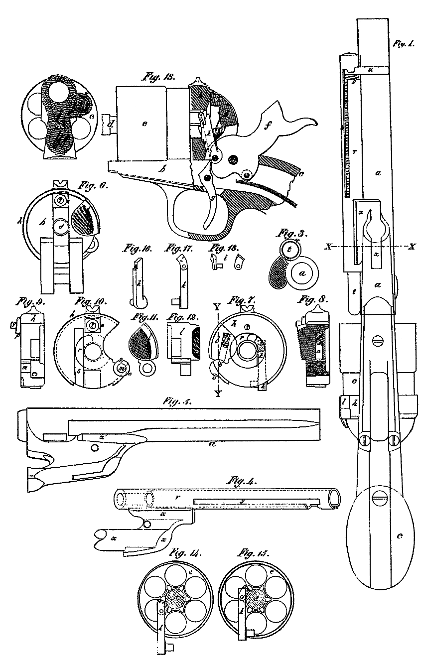
Figure 1 is a view of the under side of a Colt revolver changed so as to be adapted for flanged metallic cartridges, with my invention applied there to. Fig.2 is a cross-section of the barrel and ejecting apparatus at line X X. Fig. 3 is an end view of the muzzle of the barrel and of the ejector. Figs. 4 and 5 are perspective views of the ejector-tube or case with its flange, and of the barrel, respectively. Fig. 6 is a rear view of the pistol-lock frame, with the breech-plate and its gate in place. Figs. 7 and 8 are, respectively, a front view and section at Y Y of the breech-plate–its gate and the pawl; Figs. 9 and 10, side and rear views of breech-rings; and Figs. 11 and 12, side and edge views of the breech-plate gate. Fig. 13 is a side view, partly in section, of a portion of the pistol, showing the mechanism for rotating the cylinder. Figs. 14 and 15 aré rear views of the cylinder andjointed pawl, showing the pawl in its lowest and highest position, respectively; and Figs, 16, 17, and 18 show the jointed pawl in detail.
a is the barrel of the revolver; b, the frame; c, the stock; and d, the center-pin or axis-pin on which the cylinder e turns. f is the hammer, and g the trigger. All these parts may be made from those of an ordinary Colt revolver by changing them, as follows: First, by cutting off the rear part of the cylinder to expose the ends of the chambers. Second, by cutting away the frame at the rear of the cylinder so that a breech-plate or ring, h, may be inserted behind the cylinder. Third, by cutting off the face of the hammers. Fourth, by cutting away portions of the barrel to make place for a shell-ejector. The cylinder is further changed by cutting off the old ratchet, and forming a new one with the teeth intermediate between the chambers, so as to allow of wide teeth, and to give room between them for the insertion of the flanged cartridges. When the cylinder has six chambers the peculiar location of the ratchet-teeth, just described, prevents the use of the ordinary pawl, because, in rotating, the acting tooth of the ratchet moves out of the line of action with the pawl, which has a vertical movement only. To provide, therefore, for the rotation of the cylinder, I have devised an attachment to the end of the pawl, which is also applicable with advantage to new arms whose ratchet teeth, when being acted on, move in arcs deviating greatly from the line of action of the pawl. This consists in a movable end or bit, i, which is jointed to the end of the old pawl k. Its construction and arrangement and the way it operates on the rachet are clearly shown by Figs. 13 to 18. The jointed end of the pawl, being free to bend laterally, will follow the ratchet-tooth, on which it presses even after the tooth has turned, over beyond the side of the center-pin, around which it, rotates, and by the side of which the pawl plays. h is a breech-plate nearly filling the space between the back of the cylinder and the frame. Its general outline is circular, but it is cut away at one side sufficiently to permit the insertion of the cartridges into the cylinder. This opening is closed by a gate, l, which is jointed to the breech-plate, its pivot being a stud, m, formed in one piece with the plate. A pointed plunger, n, urged by a spiral spring, is contained in the gate, and acts to hold the gate open or shut by snapping into notches o cut in the breech-plate at the joint. A projection, p, on the back of the breech-plate, enters the channel formed in the frame b for the reception of the hammer, and prevents the plate from turning. It also increases the thickness of the plate at this point enough to furnish a sufficient bearing for the firing-pin q, by which the blow of the hammer is conveyed to the cartridge. The breech-plate has in its front face a circular central cavity, r, to receive the ratchet. The curved surface of this cavity forms a guide for the jointed end i of the pawl. A vertical groove, s, in the back of the breech-plate, intersects the cavity r and permits the pawl k to enter it. The operation of the jointed pawl in the breech-plate is illustrated in Fig. 7. t is the ejector. It consists of a straight rod furnished at its upper end with a head, an arm of which forms a thumb piece, u, for forcing it downward. The rod is contained in a tubular case, v, and its weight is sustained by a spiral spring, w. The case is furnished at its lower end with a peculiarly-shaped flange or wing, x, adapted to fit into and fill the recesses of the barrel a, originally made to receive the rammer and its lever. An opening out of the lever-recess is made at a to receive a portion of the ejector-case flange. (See Figs. 2 to 5.) The tubular part of the ejector-case lies in a bed cut along the side of the barrel. It is located in line with the gate l of the breech-plate, so that the rod t may be thrust down through the cylinder-chamber and eject the cartridges or empty shells through the gate-opening. The ejector-rod thumb-piece u protrudes from the side of the case through a longitudinal slit, y. This slit is offset laterally near the top of the case, so that the thumb-piece may, when not in use, be swung around against the barrel and then be out of the way. The lateral offset of the slit y has an outlet, z, leading to the end of the case. This outlet is located beyond the place where the thumb piece lies when turned against the barrel, and thus will not permit the ejector-rod head to be removed from the case except when the latter is taken off from the barrel; the thumb-piece may then be turned around until in line with the out let and be removed. The accidental displacement of the ejecting mechanism is thus provided against by simple means.
Having thus described the construction and operation of my invention, I disclaim as new the use of a breech-plate behind a bored-through cylinder, or of its gate, or of a cased ejector lying alongside the barrel; but
What I claim, and desire to secure by Letters Patent, is–
1. The flange x of the ejector-case when shaped and adapted, substantially as described, to fill the recesses in the barrel made for the rammer and its lever.
2. The outlet z in the ejector-case when located, as herein described, so as to prevent the removal of the ejector-rod head while the ejector-case is in place, substantially as and for the purpose set forth.
3. The projection p on the breech-plate, in combination with the firing-pin and the recess in the pistol-frame for the hammer, as set forth.
4. The movable bit i applied to and forming part of the pawl k, when operating substantially as and for the purpose specified.
In testimony whereof I have hereunto set my hand.
C. B. RICHARDS.
Witnesses:
LEWIS SHIELDON,
J. H. BOD WELL.