
US 34922
UNITED STATES PATENT OFFICE.
CHARLES DRAEGER, OF INDIANAPOLIS, INDIANA, ASSIGNOR TO HIMSELF AND JOHN OTT, OF S.AME PLACE.
IMPROVEMENT IN REPEATING FIRE-ARMS.
Specification forming part of Letters Patent No. 34,922, dated April 8, 1862.
To all whom it may concern:
Be it known that I, Charles Draeger, of the city of Indianapolis, in the county of Marion and State of Indiana, have invented a new and useful Improvement in Breech-Loading Guns; and I do hereby declare that the following is a full and exact description thereof, reference being had to the accompanying drawings, and to the letters of reference marked thereon, like letters referring to like parts.
The nature of my invention consists in the arrangement of a revolving magazine at the breech end of the barrel of the gun and the encasement of a helical spring within said magazine,which, when Wound up, and all the cartridge-chambers being supplied with powder and ball, the simple cocking of the hammer and pulling out the cartridge-plunger causes the magazine to revolve successively from one chamber to another or revolves a chamber opposite the bore of the barrel, so that the pushing the plunger forward sends the cartridge home to its proper place in the barrel for ignition. This operation can be rapidly repeated until all the charges are disposed of. It is thus Seen that a light and exceedingly effective fire-arm is produced, capable of being fired as rapidly as the ordinary revolvers, while the entire absence of all windage makes it a weapon of tremendous force and great accuracy.
To enable others skilled in the art to manufacture and use my invention, I will now proceed to describe its construction and mode of operation.
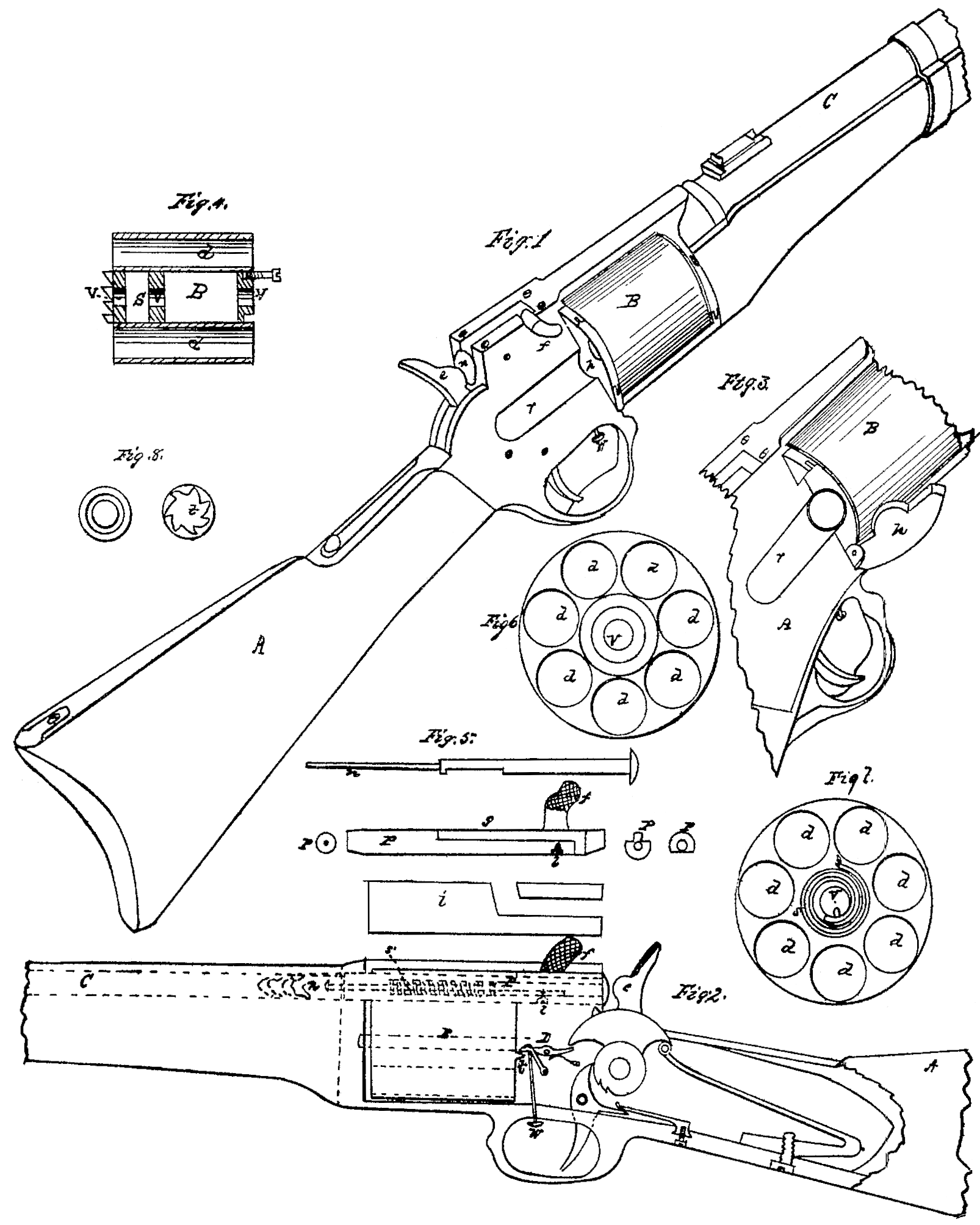
Figure 1 is a perspective view of a portion of a gun of the army pattern. Fig. 2 is a longitudinal section of Fig, 1. Fig. 3 is a small part of Fig. 1, including the revolving magazine with the cartridge-door open. Fig, 4 is a longitudinal section of the revolving cartridge-chamber. Fig.5 is a representation of the cartridge-plunder and the detonating-needle which slides within its center, and also the slotted plate that lies over this plunger and holds it to its proper place. Fig. 6 is an end view of Fig. 4; and Fig. 7 is a cross-section of same, showing the helical spring coiled around its axis and by which this magazine is revolved. It will be observed that Figs. 6 and 7 represent the magazine in natural size and containing chambers for seven charges. This latter feature may be increased to almost any extent by simply increasing the circumference of the cylinder or magazine. Fig. 8 shows the circular groove on the front end of magazine, into which a screw is forced for holding the same steady, and the right figure shows the ratchets or stops, into which a spring-dog drops, and so governs the exact intermittent rotatory movement of the magazine as it passes from one chamber to another.
A is the stock of the gun.
B is the revolving magazine, made of metal, made light and usually with seven cartridge chambers close to its periphery.
Cis the gun-barrel, of any approved size and thickness, but with a slight enlargement of the bore in the rear or breech end— say for the length of a ball and cartridge only. This is to admit of the easy insertion of cartridge and ball.
p is the cartridge plunger or loader, made of iron or steel, the same diameter of the cartridge, and with a small hollow through the center lengthwise sufficient to admit of the free play of the detonating-needle as it slides forward and back. Th slight taper at the forward end of this plunger fits snugly into a corresponding taper in the cavity in the rear end of the barrel. This is to prevent windage or escape of gas when the powder burns. This plunger has a crooked handle, f, for operating it, crooked to the right, so as to be out of the line of sight when taking aim. Besides serving the purpose of a handle, it answers also as a brace or wedge when it is turned into the inclined lateral slot in the top piece, i, where it firmly resists the reaction of the ignited powder within the barrel.
The detonating-needle n may be seen in place by the dotted lines in Fig. 2 passing clear through the cartridge-plunger far enough to reach the fulminating material in the cartridge. A spiral spring surrounds it for the purpose of springing it back when the hammer is cocked, and thereby bringing its point within the plunger, so that the magazine can freely revolve. When a charge is pushed home this needle stands clear of all contact with it, and is only driven into its base by the hammer e. A short bevel on the under side, at the backend of the plunger p, allows a small projection on the cock-tumbler, in front of the cock, to catch upon the head of the needle n, and this serves to liberate it by giving it a start, so that the spring which is around it may throw it out, as spoken of already.
The cartridge door his shut or down in Fig. 1 and thrown open in Fig. 3. It is opened to put the cartridges into the chambers d d d, the recess r being made for their free admission. When they are all in this door is closed and holds them there. Another hinged door may be seen at the front end of the revolving magazine in immediate line with h. This is only used when a cartridge fails fire and it is necessary to remove,which is done by simply pushing it out backward, or to empty the gun when not in use.
t are ratchets on the back end of revolving magazine B, into which the dog-lever d’ catches, and is again liberated when the hammer e is down by means of a projection on the front side of the lock-tumbler. The thumb spring W is secured to the under side of the front end of this dog-lever, so that the magazine may be freed at any time by a simple pressure upon it inside the trigger-guard.
The little cross-sections in Fig. 5 are to show the half-grooves in the upper sides of plunger P, into which the points of two screws enter as guides for steadying the plunger and pre went rocking; also, the extreme right-hand one of these Sections shows the bevel on the end of plunger where the point on the lock tumbler trips the needle n for purposes heretofore mentioned. The temper-screw l passes its point into a groove on the under side of needle n and limits its play back and forth. The spiral springs throws the needle clear of the cartridge and holds it there until it is driven into the cartridge by the hammer e.
The parts of this gun are few, and those parts are all simple in construction and in no way more liable to break or get out of repair than are those of the ordinary and generally used guns. It’s combined operation is very simple and easily understood, and a very slight experience will enable the operator to fire it about thirty times in a minute. Its range is as great as is possible to reach with a given quantity of ammunition, having none of the defects of other breech-loaders, and being superior in some particulars to even muzzle-loaders, inasmuch as the ball is more effectually forced into the grooves of the rife.
What I claim as new, and desire to secure by Letters Patent, is—
1. The arrangement of a cartridge-magazine, B, revolving on a longitudinal axis, as shown.
2. A plunger, P, and needle u, constructed as set forth, and combined in their operation with a revolving magazine, as stated substantially.
3. The helical spring S, when used, as shown, for the purpose of rotating the cartridge-magazine B.
CHARLES DRAEGER.
Witnesses:
Ignatius Brown,
James N. Sweetser.