
US 34226
UNITED STATES PATENT OFFICE.
C. R. ALSOP, OF MIDDLETOWN, CONNECTICUT, ASSIGNOR TO J. W. ALSOP, OF NEW YORK, N. Y.
IMPROVEMENT IN REVOLVING FIRE-ARMS.
Specification forming part of Letters Patent No. 34,226, dated January 21, 1862.
To all whom it may concern:
Be it known that I, CHARLES, R. ALSOP, of Middletown, in the county of Middlesex and State of Connecticut, have invented certain new and useful Improvements in that class of Fire-Arms known as “Revolvers;” and I do hereby declare that the following is a full, clear, and exact description of the same, reference being had to the accompanying drawings, forming part of this specification, in which–
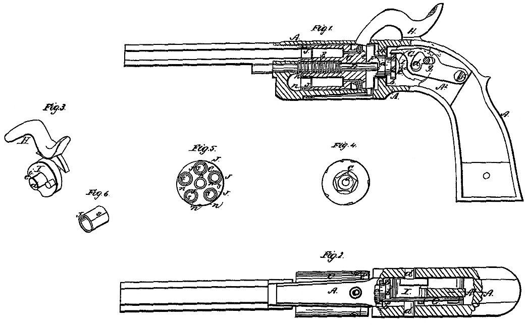
Figure 1 is a longitudinal section of a pistol with my improvements. Fig. 2 is a top view of the same, partly in section. Fig. 3 is a perspective view of the hammer and its attached cam for forcing up the cylinder. Fig. 4 is a rear end view of the cylinder. Fig. 5 is a front end view of the same. Fig. 6 is a perspective view of one of the gas-rings.
Similar letters of reference indicate corresponding parts in the several figures.
To enable others skilled in the art to make and use my invention, I will proceed to describe its construction and operation.
A is the metal frame, of the form generally adopted for the frames of revolvers.
B is the barrel.
C is the cylinder, fitted to revolve on the axis pin D in a well-known manner, and having applied between it and the front of the frame the spring E for forcing it back clear of the barrel preparatory to its rotary movements.
F is the rotating recoil-shield, having its journal a fitted to a bearing in the cross-piece A’ of the frame, having on the rear of said journal the ratchet-teeth b b, upon which the rotating dog G acts to produce the rotation of the cylinder, which is caused to rotate with the shield by a pin, c, on the rear of the cylinder entering a recess in the face of the shield in a manner common to other revolvers.
H is the hammer, arranged to work upon a pin, d, passing through the stock in the usual manner. I is the cam for forcing the cylinder up toward the barrel. This cam may be made of a separate piece of steel and secured by screws, rivets, or other suitable means to one side of the butt of the hammer, or may be formed upon and of the same piece of metal with the hammer itself; or, in the case of an outside hammer, it may be formed upon or secured to the tumbler of the lock, or otherwise secured to the shaft of the hammer, and so attached to the hammer and compelled to move with it. This cam has the greatest portion of its circumference circular and concentric with its pin d, and has a recess, as shown at e. The said cam is situated immediately in front of a fixed brace, A2, which is cast with the frame A, and the front of the said brace is hollowed out to form a bearing for the cam, which is fitted so easily to the pin d that it may always bear against the said brace. The full diameter of the larger circular portion of the said cam is such that when interposed between the brace and the rounded rear end of the journal a, as it is when the hammer is down, the said calm will hold the cylinder so far forward as to cause whichever chamber is in line with the barrel to fit close up to the rear muzzle of the latter. The recess e need only be of such depth that when it is presented opposite the rounded end of the journal a it will allow the spring E to force back the cylinder far enough to let it rotate clear of the barrel, and said recess is so arranged relatively to the hammer that before the hammer has been moved far from the nipple toward the position in which it is cocked it brings the said recess opposite to the rounded end of the journal, and so permits the cylinder to move back before the action of the cocking-dog on the ratchet-teeth b b commences. The fall of the hammer brings the step i at the commencement of the recess into action on the extremity of the journal ct, and so forces the cylinder up to the barrel before the hammer strikes the nipple. Care should be taken in the construction that the axes of the pins D and d should be in the same plane, that the action of the can may be directly in the line of the axis of the cylinder. This mode of applying the cam is intended more particularly for small-sized pistols, which are to be cocked by the direct application of the hand to the hammer. The hammer is to have the mainspring and trigger applied in the manner common to fire-arms which are cocked in that way, and therefore I have not represented those parts in the drawings, but confined myself to the representation of the parts to which my invention relates and the parts necessary to explain it. The rotating dog G is arranged to swing upon a fixed pin, f, and is operated by means. of a pin, g, attached to the cam I.
J J are the gas-rings, differing from those commonly employed in the chambers of revolvers in being cut or open longitudinally, as shown at s s in Figs. 5 and 6. They may be made each of a piece of steel plate rolled up, or be turned out of a solid piece of steel, and afterward cut longitudinally, and may be made so that the edges of the split lap together in beveled form, as shown in Figs. 5 and 6,or merely meet each other. The front portions of the chambers are counterbored to the requisite depth for the reception of these rings, which are crowded tightly into the so counterbored portions, and the rear portion of the barrel is counterbored for the reception of the front ends of the said rings, which either protrude from the said chambers or have the fronts of the chambers countersunk around them, as shown at n n in Figs. 1 and 5, for the reception of the rear end of the barrel. These rings, instead of being simply driven forward toward the barrel by the force of the explosion of the charges in the chambers, are expanded by such force, and so caused to be pressed laterally against the counter-bores of the cylinder and barrel, and make a more perfect joint than when merely pressed forward.
I do not here intend to claim broadly the use of an oscillating cam to force forward the cylinder orbreech toward the barrel preparatory to the firing of the piece; nor do I claim broadly the use of gas-rings applied to the cylinder; nor do I claim broadly the construction of the hammer with a cam for the purpose of driving up the chamber against the barrel by the fall of the hammer; but
What I claim as my invention, and desire to secure by Letters Patent, is–
The combination of the hammer-cam I with the rearward extremity of the axis-pin D, in the manner and for the purpose herein shown and described.
CHAS. R. ALSOP.
Witnesses:
MARIA. W. BARNES,
JONATHAN BARNES.