
US 38279
UNITED STATES PATENT OFFICE.
CHRISTOPHER C. BRAND, OF NORWICH, CONNECTICUT.
IMPROVEMENT IN REVOLVING FIRE-ARMS.
Specification forming part of Letters Patent No. 38,279, dated April 28, 1863.
To all whom it may concern:
Be it known that I, Christopher, C. Brand, of Norwich, in the county of New London and State of Connecticut, have invented certain new and useful Improvements in Repeating Fire-Arms; and I hereby declare that the following is a full, clear, and exact description of the same, reference being had to the accompanying drawings, in which—
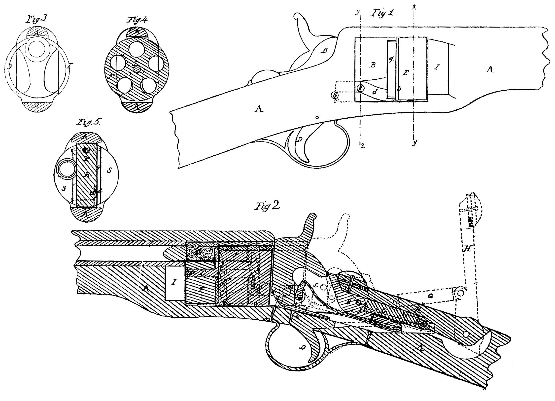
Figure 1 is a side elevation of that part of a repeating rifle which embodies my improvements. Fig.2 represents a longitudinal section of the same according to a vertical plane passing through the axis of the barrel, the black lines in said figure indicating the breech closed against the butt of the barrel, while the blue lines represent it open. Figs. 3 and 4 are transverse sections of the same at the line x y of Fig. 1, and looking toward the barrel. In the former figure the breech is supposed to be removed, in the latter closed. Fig. 5 represents a transverse section of the same at the line y z of Fig. 1, also looking toward the barrel.
My invention relates to that class of repeating fire-arms which are adapted to the use of metallic cartridges that are inserted into the revolving cylinder at its butt; and my invention consists, first, in the combination of a cylinder shorter than the cartridge-case used therein, and having, when operated, a compound back-and-forth and rotary motion, and a lock, in such manner that these two move together in a recess or recesses in the stock, While the stock remains permanently connected with the barrel of the fire-arm; second, in the combination, with a cylinder having a sliding and rotary motion and lock moving with the cylinder to and from the barrel in a recess in the stock, of a trigger permanently connected with the stock, the arrangement being such that the hammer can be operated thereby only when the cylinder is closed against the barrel; third, in the combination, with a sliding revolving cylinder sliding with the lock in a recess or recesses in the stock, of a lock-case of such construction that it performs the functions of guiding the cylinder and of protecting the lock while moving to and from the barrel; fourth, in the combination, with a sliding revolving cylinder and a lock-containing guide-case, when moving together in recesses in the stock to and from the barrel, of a percussion-pin located within said case to transmit the blow of the hammer to the cartridge in the barrel; fifth, in the combination of a lever which moves the sliding and revolving cylinder in a recess of the stock to and from the barrel and of a mechanism for operating the revolution of the cylinder under such arrangement that when the said lever is raised on a pivot on the rear end thereof the cylinder is drawn back from and in line with the barrel and rotated upon its axis.
The fire-arm represented in the accompanying drawings contains several essential features for which Letters Patent of the United States were issued to me on the 23d day of September, 1862, and the main feature consists in making the length of the revolving cylinder shorter than the length of the cartridge-case, so that the front end of a cartridge when in a chamber of the cylinder protrudes in front of it, and in combining the said cylinder, with the barrel by means of mechanism in such manner that the cylinder is withdrawn from the butt of the barrel prior to its rotation sufficiently to permit the end of the cartridge to turn, and is moved toward the barrel to close the breech and insert the protruding end of the cartridge into the butt of the barrel. By this combination the front end of the cartridge-case is caused to overlap the joint of the breech at the time the charge is fired to prevent the escape thereat of any matter from within. In this instance the stock A is recessed in its upper portion to receive within its cavity the lock L, snugly incased in a casing, B, open on its under side, so that the sear C of the lock may be operated upon by the trigger D and closed at the sides and on top, allowing only the cock of the hammer to protrude therefrom, so that the hammer may from without be cocked and its action otherwise controlled. This casing B extends in front of the lock the length of the path which the lock in its motion to and from the barrel describes, and is fitted into a portion of the stock, which is recessed at the sides, constituting a guide-bolt, where by the lock and the cylinder are guided in their reciprocating movement. This lock-case or guide-bolt is therefore guided on top and bottom by both that portion of the stock which is recessed upon its sides and that which is recessed on top in direction of its depth.
To the front end of the casing is fixed a spindle, E, upon which is mounted the revolving cylinder, F, the recess from side to side in the stock being sufficiently large to admit of the cylinder having within it its reciprocating and rotary motion. To the rear end of the casing there is pivoted the link G, by means of which the casing is connected with the lever H, whose rear end is pivoted in the extreme rear end of the recess in the top of the stock, and the dimensions of the parts are such that when the lever is raised, as shown in blue lines in Fig. 2, the revolving cylinder and lock are moved back from the butt of the barrel, leaving ample space between the front end of the cylinder and the barrel for the projecting ends of the cartridges to turn into line with the barrel without striking. By depressing the lever the cylinder is brought in contact with the barrel, its uppermost chamber being in line therewith, while the lock is brought in such relative position to the trigger in the stock as that the sear in the lock is in juxtaposition there with and ready to be operated upon by the trigger.
The front ends of the cartridges that project from the cylinder are protected against injury by a guard-ring, I, secured to the stock beneath the barrel, which is designed to receive the ends of the cartridges when the breech is closed by the forward movement of the cylinder. In order to revolve the cylinder, a ratchet-wheel, b, is fitted to the rear or butt of the cylinder. The teeth of this ratchet-wheel are operated upon by a spring-pawl, c, which is pivoted to one arm of a vibrating pawl, d, pivoted in its turn to the outside of the lock-case, and deriving its vibratory motion from a pin or stud, f, fixed to and projecting from the interior face of the recess of the stock. The vibratory pawl is so shaped as to be operated by the pin or stud during that part of the backward movement of the cylinder and its appurtenances when the ends of the cartridges are clear of the barrel. Before the cylinder reaches its most backward position the incline or cam side of the vibratory pawl comes in contact with the pin, so that the continued movement of the cylinder by the lever causes the pawl-lever to vibrate and to rotate the cylinder. This rotation of the cylinder continues until the chamber previously in line with the barrel is moved past it and a succeeding chamber is brought into line with the barrel. When this is accomplished the further rotation of the cylinder and its further movement backward by the lever are simultaneously stopped by the projecting end g of the shields coming in contact with the bot tom of the side recess in the stock. The rear end of the vibrating pawl is now in such a position that when the cylinder is moved for Ward by the lever H the pin f comes in contact With the rear end of the vibrating pawl sufficiently, before the cylinder reaches its place at the butt of the barrel to move the pawl-lever the distance required to withdraw the pawl from the ratchet-tooth with which it was in contact and engage it with the tooth appertaining to the succeeding chamber of the cylinder.
In order to transmit the blow from the hammer through the intermediate lock-case or guide-bolt to the cartridge, I provide the said lock-case with a percussion-pin, P, located in an orifice in the body of the lock-case in line with the percussion-hammer and the flange of the cartridge to be struck. This percussion pin is caused by means of a spiral spring to slightly protrude from the face of the block opposite the hammer, while its front end is flush with the face of the case which is opposite the cylinder.
Having thus fully described my invention and the manner in which the same is carried into effect, I shall state my claims as follows:
1. The combination of a cylinder shorter than the length of the cartridge-case used there in, and having when operated a compound back-and-forth and rotary motion, and a lock in such manner that these two move together in a recess or recesses in the stock, while the stock remains permanently connected with the barrel of the fire-arm, substantially as hereinbefore set forth.
2. The combination, with a cylinder having a sliding and rotary motion and a lock moving with the cylinder to and from the barrel in a recess in the stock, of a trigger permanently connected with the stock, the whole being arranged to operate substantially as set forth.
3. The combination, with a sliding revolving cylinder sliding with the lock in a recess or recesses in the stock, of a lock-case of such construction that it performs the functions of guiding the cylinder and protecting the lock while moving to and from the barrel, substantially as herein set forth.
4. The combination, with a sliding revolving cylinder and a lock-containing guide-case, when moving together in recesses in the stock to and from the barrel, of a percussion-pin located within said case to transmit the blow of the hammer to the cartridge in the barrel, substantially as set forth.
5. The combination of a lever which moves the sliding and revolving cylinder in a recess of the stock to and from the barrel and of a mechanism for so operating the revolution of the cylinder under such arrangement that when the said lever is raised on a pivot on the rear end thereof the cylinder is drawn back and in line with the barrel and rotated upon its axis, substantially as herein set forth.
In testimony whereof I have signed my name to this specification before two subscribing witnesses.
C. C. BRAND.
Witnesses:
A. Pollok,
Wm. H. Harrison.