
British Patent No. 6909
Practical revolving firearm, repeated in US patent of 1836
Patent for Certain Improvements Applicable to Fire Arms, No. 6909, granted to Samuel Colt by His Majesty’s Patent Office in United Kingdom, October 22, 1835.
The first practical revolving firearm (a revolver with a mechanically rotating cylinder) was patented by Samuel Colt in Great Britain on October 22, 1835. Colt filed for copyright protection in Europe before applying for a patent in the United States because of the peculiarities of international patent laws. Although an American patent would have precluded the filing for a patent in England or France, no such stipulation prevented him from filing in the United States after securing his foreign patent rights. After the British patent was granted on October 22 and the French patent on November 16, 1835, Colt secured an American patent for his revolver on February 25, 1836. Colt’s patents effectively gave him a monopoly on revolvers until 1857.
A.D. 1835 N° 6909.
Revolving Fire-arms.
COLT’S SPECIFICATION.
TO ALL TO WHOM THESE PRESENTS SHALL COME, I, SAMUEL COLT, of Ludgate Hill, in the City of London, Gentleman, send greeting.
WHEREAS His present most Excellent Majesty King William the Fourth, by His Letters Patent under the Great Seal of Great Britain, bearing date at Westminster, the Twenty-second day of October, in the sixth year of His reign, did, for Himself, His heirs and successors, give and grant unto me, the said Samuel Colt, His especial license, full power, sole privilege and authority, that I, the said Samuel Colt, my exors, admors, and assigns, or such others as I, the said Samuel Colt, my exors, admors, or assigns, should at any time agree with, and no others, from time to time and at all times during the term of years therein expressed, should and lawfully might make, use, exercise, and vend, within England, Wales, and the Town of Berwick upon Tweed, my Invention of “Certain Improvements Applicable to Fire-Arms;” in which said Letters Patent is contained a proviso, that I, the said Samuel Colt, shall cause a particular description of the nature of my said Invention, and in what manner the same is to be performed, to be inrolled in His said Majesty’s High Court of Chancery within six calendar months next and immediately after the date of the said in part recited Letters Patent, as in and by the same, reference being thereunto had, will more fully and at large appear.
NOW KNOW YE, that in compliance with the said proviso, I, the said Samuel Colt, do hereby declare that the nature of my said Invention of certain improvements applicable to fire-arms, and the manner in which the same is to be carried into effect, are fully set forth and explained in the following description thereof, as elucidated by the Drawings hereunto annexed, reference being had to the figures and letters marked on the Drawings in correspondence with the same figures and letters herein contained, that is to say: –
My Invention consists, First, in the adaptation and application of certain levers, lifters, slides, plates, connecting pieces, springs, a ratchet, a mandril or arbor, a shackle, and other apparatus, as herein-after particularly shewn and described, to that species of gun and pistol having a cylindrical breech piece revolving round an axis parallel to the axis of the barrel, in which breech piece six or more chambers are bored, each capable of containing a charge of powder and shot, and which charges by the revolution of the cylinder may be brought successively in a line with the bore of the barrel, through which they may he discharged one at a time; the object of my principles, adaptations, and applications being to cause the said cylinder to revolve the distance from centre to centre of two contiguous chambers by the action of cocking the gun or pistol, and by the same action to lock the cylinder firmly in its place when so brought, and thus that no care or attention on the part of the person using the fire arms is required in order to bring the charges into the proper place for being discharged through the barrel.
Secondly, in a peculiar mode of securing the revolving breech piece, that it may revolve freely and yet be discharged safely.
Thirdly, in protecting the lock and connecting works from wet and from the smoke of the explosions, by a peculiar shield which will allow the smoke to escape without annoyance to the person using the gun or pistol, which shield also receives and resists the recoil of the revolving cylinder.
Fourthly, in placing the axis of the aperture of the percussion tube in a right line with the axis of the chamber.
Colt’s Improvements in Revolving Fire-arms.
Fifthly, in a ready method of securing the barrel to the cylinder, and of detaching it at pleasure, so that the loading of the chambers may be performed with facility and dispatch.
Sixthly, in effectually separating the recesses in which the percussion tubes are placed from each other, so as to prevent fire communicating from the exploding cap to the adjoining ones.
And seventhly, (in the case of guns discharged from the shoulder) in the use of a ram or sliding piece to receive the blow of the hammer and communicate the same to the percussion cap, whereby more space is obtained between the revolving cylinder and the hammer for the apparatus. And the manner in which I carry into effect these my improvements upon fire arms is shown and explained as follows:
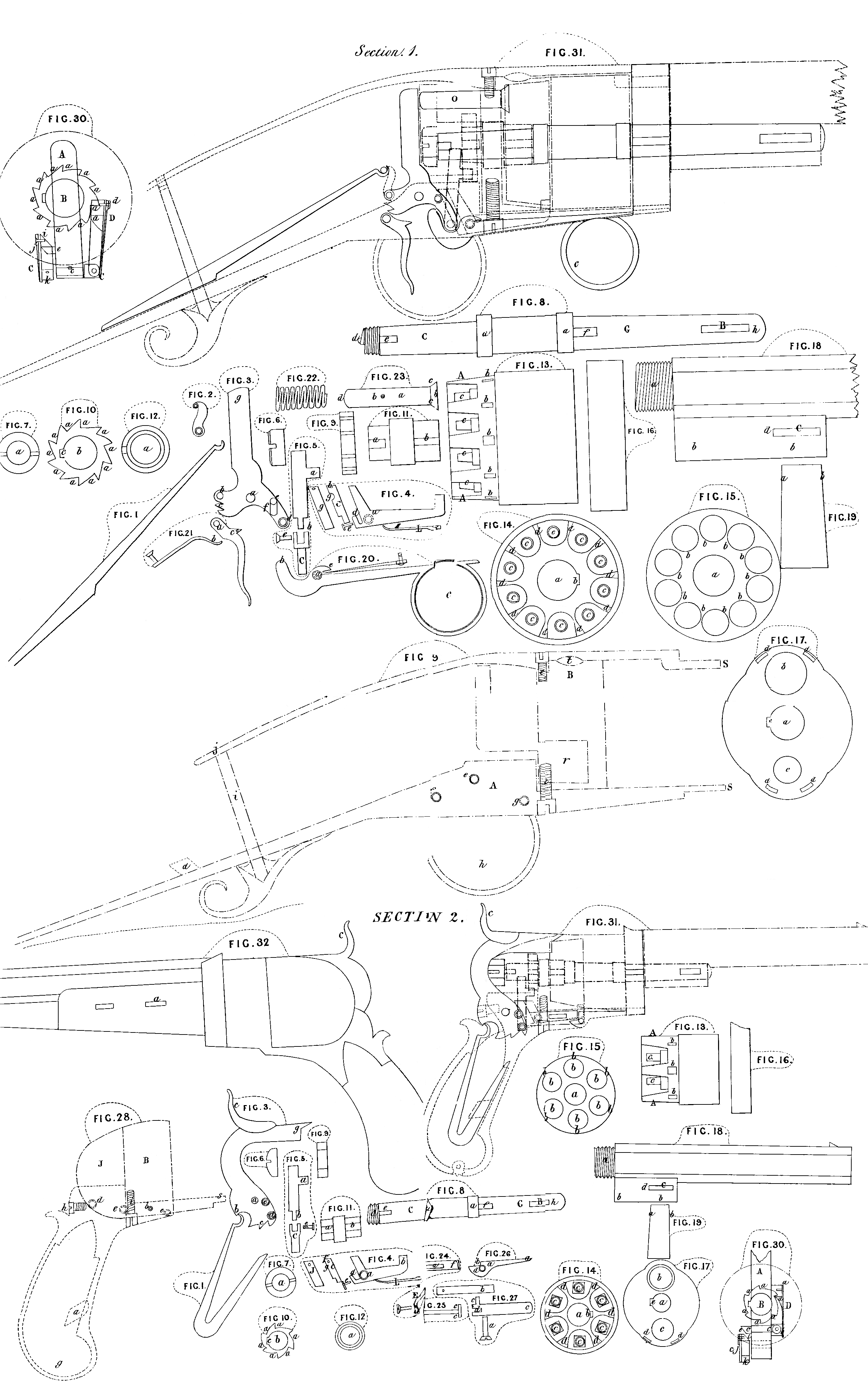
Section 1, represents the parts necessary to the application of my improvements to fire arms discharged from the shoulder; section 2, represents the parts necessary to the application of my improvements to pistols. In order to a clear explanation, I will first describe the parts and their connections, shewn in both sections; then those peculiar to shoulder-arms, as shewn only in section 1; and after which, such parts as belong to pistols, as contained in section 2. The parts shewn in both sections are Figure 1, the main spring; Figure 2, the stirrup, which connects the main spring to the hammer; the stirrup is omitted in section 2, for the sake of shewing a different form of action of the spring on the hammer; Figure 3, the hammer; its fulcrum is at a; at b, is attached to the stirrup (Figure 2); at c, are the notches for the trigger; d, is the place where the lifter (Figure 5) is attached; e, is a stud projecting from the side of the hammer that operates on the key. Figure 4, is the key that locks the cylinder (Figure 13); its fulcrum is at a; b; is the bolt at the end of the long arm which enters the mortice b, b, & c. in the cylinder (Figure 13.) The catch C, is attached to the arm d, of the key by the pin c, passing through its lower end to form a hinge, which permits the upper end of the catch to move laterally; g, is the plate acted upon by the stud c, on the hammer (Figure 3) to draw out the bolt b, of the key from the mortice in the cylinder (Figure 13); J, is a spring rivetted to the catch c, at f; the lower end of which spring acts below the hinge to bring the upper part back to its place, when the stud e, on the hammer (Figure 3) has passed down to the place g, of the catch C; L, is a spring (attached to the lock plate) that forces the arm b, into the mortices b, in the cylinder (Figure 13). Figure 5, is the lifter which turns the cylinder (Figure 13); the arm a, acts on the teeth of the ratchet (Figure 10); the round part of the arm C, passes through the hammer (Figure 3) at d, in which it is permitted to turn sufficiently to keep the arm a, in a proper situation to act under the teeth of the ratchet (Figure l 0). The lifter is joined at b, with the forked end of the arm C, by the pin e, which forms a hinge to allow the arm a, some lateral motion in respect of the hammer, whereby the lifter may accommodate itself to the curvature of the ratchet and depth of its tooth. Figure 6, is the nutt which holds the arbor (Figure 8) in the shield (B, Figure 29). Figure 7, is an end view of the nutt (Figure 6); a, is the place where it screws on to the arbor. Figure 8, is the arbor on which the cylinder (Figure 13) and shackle (Figure 11) turn, and which arbor connects the barrel (Figure 18) with the cylinder (Figure 13); a, a, are the bearings of the cylinder; B, is n mortice, through which the wedge (Figure 19) enters to connect the barrel (Figure 18) with the cylinder (Figure 13); C, is the part on which the shackle (Figure 11) turns; d, is the screw on which the nutt (Figures 6 and 7) is screwed to fasten the arbor firmly to the shield (B, Figure 29); e, is a feather or ward which enters a groove in the shield (Figure 29) to prevent the arbor from turning; f, is a feather or ward which enters a groove in the plate (Figure 17) to prevent the plate from turning. The end G, passes through the plate (Figures l6 and l 7), and through a projection under the barrel (Figure 18), to connect them to the cylinder (Figure 13). Figure 9, is the ratchet wheel which is placed on the shackle (Figure 11 ). Figure 10, is an end view of the ratchet; a, a, &c. are the teeth which are acted on by the arm a, of the lifter (Figure 5), to cause it to turn the shackle (Figure 11), which enters at b; and c, is a groove that receives the ward a, of the shackle. Figure 11, is the shackle which connects the ratchet (Figure 9) to the cylinder (Figures 13 and 14); a, is a ward which enters the groove c, in the ratchet (Figure 10), and causes the shackle to move with the ratchet; b, is a ward which enters a corresponding grove in the cylinder (Figure 14), to prevent it from turning except with the shackle and ratchet. Figure 12, is an end view of the shackle; the arbor (Figure 8) on which the shackle turns passes through its central aperture a. Figure 13, is the cylinder in which are chambers for the charges; c, c, &e. are tubes screwed into the bottom of the chambers on which the percussion caps are placed; b; b, &c. are mortices to receive the bolt b, of the key (Figure 4) which locks the cylinder when a chamber is directly opposite the barrel (Figure 18). The shield B (Figures 28 and 29) is fixed over the end A, of the cylinder, to protect the percussion cap from moisture. Figure 14, represents the back end of the cylinder (Figure 13). The shackle (Figure 11) enters the central apertures a, and the ward b of the shackle enters the mortice b, of the cylinder, which causes them to turn together; c, c, &c. are ends of the percussion tubes on which are placed the percussion caps; d, d, &c, are partitions between the tubes which prevent fire communicating from the exploding caps to the adjoining ones. Figure 15, represents the forward end of the cylinder (Figure 13); a, is the middle aperture through which the arbor (Figure 8) passes; b, b, &c. are the chambers for the charges. Figure 16, is the plate which covers the forward end of the cylinder (Figures 13 and 15) to protect the charges from moisture, and to which plate the barrel (Figure 18) is firmly secured. Figure 17, represents the forward view of the plate (Figure 16); a, is an aperture through which the end g, of the arbor (Figure 8) passes; e, is a groove to receive the ward f, of the arbor (Figure 8); at b, the barrel (Figure 18) is attached; c, is a hole through which the charges may be passed into the chambers b, b, &e. in the cylinder (Figure 15), when it is desirable to omit taking off the· barrel and plate; and d, d, &c. are mortices to receive the ends s, s, of the guards or lock plates (Figures 23 and 29). Figure 18, is the barrel which gives direction to the charge; a, is the end that screws into the plate at b (Figure 17); b, b, is a projection under the barre1 which receives the end G, of the arbor (Figure 8); C, is a mortice for admitting the wedge (Figure 19). Figure 19; is the wedge which passes through the mortice C, of the barrel (Figure 18), and the mortice B, in the arbor (Figure 8), to hold the plate (Figure 16), and the barrel (Figure 18), in contact with the cylinder (Figure 13), and the cylinder in contact with the shield (Figure 29); the small end of the wedge enters the mortices, and when it is pressed into them the edge a, acts on the end d, of the mortice C, in the barrel (Figure 18), the other edge b, acts on the end h, of the mortice B, in the arbor (Figure 8), which causes the plate (Figure 16), and the barrel (Figure 18), to be drawn to the fore end of the cylinder (Figures 13 and 15) with any requisite degree of tightness. Parts shewn only in section 1, as not adapted to pistols:-Figure 20, is the lever used for drawing back the hammer; its fulcrum is at a; b, is the part that acts at f, on the hammer (Figure 3), and raises it when the end c, of the lever is drawn down; f, is a spring fastened in the lock plate (A, Figure 29), which spring acts at e, on the lever, and draws the end c, to its place against the lock plate; after the hammer has been drawn back to its proper position for being let off for exploding the percussion caps. Figure 21, is the trigger; its fulcrum is at a; b, is a spring fastened to the lock plate that forces the catch c, of the trigger into the notches c, of the hammer (Figure 3). Figure 22, is the spiral spring that draws the ram (Figure 23) from the tubes c, c,&c in the cylinder (Figure 13), and permits the cylinder to turn when the end g, of the hammer (Figure 3) is drawn back. Figure 23, is the ram for conveying the force of the hammer to the percussion cap. The spiral spring (Figure 22) is placed on it at a; b, is a pin against which the spiral spring acts to force back the ram, the other end of which spring abuts against the back part of the shield; at the end c, of the ram there is a shoulder that comes against the shield (B, Figure 29) to prevent the coiled spring from drawing the ram too far back from the percussion cap. The end g, of the hammer (Figure 3) strikes the end d; of the ram, the other end f, of which discharges the percussion cap.
Parts peculiar to pistols shewn only in section 2: -Figure 24, is the connecting rod or sliding piece between the hammer (Figure 3), and the trigger (Figure 26); a, is a slot through which a pin passes to hold the connecting rod in its place, and to allow it a longitudinal motion. The face of the end b, is oblique, so that when the part d, of the hammer (Figure 3) is raised, it commences to act at the bottom part c, of the oblique face of the connecting rod, and causes it to slide forward; the other end f, of which connecting rod operates at b, on the secret trigger (Figure 26). E, is a forked spring fastened to the lock plate (Figure 28), the upper end of which forked spring hooks into the end b, of the connecting rod to force its catch d, into the notches c, on the hammer (Figure 3), and hold it back when the notches are brought opposite the catch. Figure 25, is a view of the upper side of the connecting rod; a, a, the shoulders against which the prongs of the spring (E, Figure 24) press; c, c, the shoulders behind which the fork of the trigger acts. Figure 26, is the secret trigger to let off the lock; its fulcrum is at a; at b, the end f, of the connecting rod (Figure 24) acts when it is moved forward by the hammer (Figure 3), which causes the end c, of the trigger to be thrown into a suitable position for the finger. Figure 27, is a view of the upper side of the trigger (Figure 26); it turns on the pin a; b, is a spring (fastened to the lock plate) to hold the secret trigger in its place, by acting on the projection c; d, is the fork that acts behind the shoulders c, c, of the connecting rod (Figure 25), so that by pressing the finger on the end c, of the trigger, the catch d,, of the connecting rod (Figure 24) is drawn from the notch c, of the hammer (Figure 3), and the main spring (Figure 1) forces the end g, of the hammer (Figure 3) against the percussion cap, which causes the load to be discharged, as is seen in the transparency (Figure 31 ). Figure 28, represents the handle, lock plate, and shield; the part colored yellow is the shield; the part colored red is the handle and lock plate; the main spring (Figure l) is fastened at a; the hammer (Figure 3) turns at d; the key (Figure 4) at c; the connecting rod (Figure 24) slides on the pin at b; and the trigger (Figure 26) turns at c. The forked end of the lock plate s, enters the mortices d, d, & c. in the plate (Figure 17). At g, is a hinge to permit the back part of the handle to open when the screw h, is drawn. The screw i, connects the handle and lock plate with the shield; the forward part B, of the shield covers the hind part A, of the cylinder (Figure 13), and protects the percussion caps from moisture. The back part J, forms a complete cover for the lock, and protects it from the smoke of the percussion caps and from moisture. The form of the inside of the shield and lock plates must be such as to allow the parts their respective motions as seen in the transparent view (Figure 31). Figure 29, (section 1,) is the lock plate, shields, and guards, suited to guns discharged from the shoulder. A, is the lock plate to which the main spring (Figure 1) is attached, at d; the hammer (Figure 3) at e; the trigger (Figure 21) at f; the key (Figure 4), and the lever (Figure 26), at g. At h, is the guard for the trigger. i, is a bolt that passes through the lock plate and stock, and screws to the upper guard at j, to connect them together; the forked ends of the lock plate S, S, enter the mortices d, d, &c. in the plate (Figure 17). l, l, arc screws which connect the lock plate and guards to the shield B. The forward part of the shield covers the end A, of the cylinder (Figure 13), and protects it from moisture. Between the ratchet (Figure 9), and cylinder (Figure 13), is a partition on the shield to prevent the smoke of the percussion caps getting to the lock. r, is a sliding shutter over an opening to the tubes for the purpose of putting on percussion caps. t, is a hole in the top of the shield for the smoke of the percussion caps to escape. The interior of the shield and lock plate must be suited to the lock, as is seen in the transparent view (Figure 31). Figure 30, sections l, and 2, represent (by an end view) the relative position of the key (Figure 4); the lifter (Fig. 5); the ratchet (Fig. 10); and hammer (Fig. 3). The black line A, represents the hammer. B, in the centre is the position of the ratchet. C, is the key which is operated on by the stud e, and the hammer A. The end of the stud e, and the end i, of the back part of the key are both cut off’ obliquely, that they may, when brought in contact, cause the upper end of the catch of the key to move laterally and permit the stud e, to pass down to its place behind it again, when, by means of the spring j, which is fastened to the upper end i, of the catch, and acts below the joint at k, it is brought back to its former position before the stud e, on the hammer A. D, is the lifter. The arm c, passes through the hammer (A), where it is secured by a pin acting in a groove in the arm to prevent it from coming out. b, is the hinge that allows the upper end a lateral motion. a, is the arm which acts in the teeth a, a, &c. of the ratchet B. At d, a spring is attached that keeps the arm a, into the teeth of the ratchet by the action of its other end on the lower part of the hinge b. Figure 31, sections 1, and 2, shew, by a transparency, the relative position of all the parts combined; the colour and form of the outlines of each correspond with the colour and form of their separate parts. To work the lock of the gun draw on the lever at c, (Figure 31,) and as the arm d, of the hammer (Figure 3) is raised, the stud e, presses against the end g, of the key (Figure 4), and consequently its bolt b, is withdrawn from the mortice b of the cylinder (Figure 13), at which time the lifter (Figure 5) (being connected with the hammer (Figure 3) at a) is raised, and its arm a, catches in a tooth of the ratchet (Figures 9 and 10), which, being connected with the cylinder (Figure 13), by means of the shackle (Figure 11) causes the cylinder (Figure 13) to turn, and before the succeeding chamber is brought opposite the barrel (Figure 18), the stud e, on the hammer (Figure 3) passes the top of the catch of the key (Figure 4), and when the hammer (Figure 3) is drawn back to its proper position for discharging, then the succeeding chamber in the cylinder (Figure 13) has come directly opposite the caliber of the barrel (Figure 18). In this position the bolt b, of the key (Figure 4) is forced by the spring L, Fig. 4, into the succeeding mortice in the cylinder (Figure 13), and holds it until the pulling back of the hammer is repeated. By pulling the trigger the mainspring (Figure 1) forces the hammer (Figure 3) forward to its former position, and the upper end g, discharges the percussion cap. During which operation the lifter (by means of its lateral motion to the left) passes below the succeeding tooth on the ratchet, and by means of the lateral motion to the right of the catch C, of the key (Figure 4), the pin e, on the hammer (Figure 3) is permitted to pass below it again. A repetition of the same motions produce the same effects. To work the pistol lock the cock is drawn back, which, by its lower part, acts against the oblique back-end of the connecting rod, the front end of which presses against the shoulder of the trigger and throws its tail down into the position for discharging. The operation of the key, lifter, and other parts for unlocking, turning, and relocking the cylinder are similar to that for the gun, and the lock is let off by pulling the trigger, as in the gun, when the various parts will be restored to their places for a repetition of the working. Figure 32, represents a pistol when fitted for use. To load the gun or pistol it is only necessary to draw out the wedge a, (Figure 19,) which will liberate the barrel (Figure 18); then, by withdrawing the bolt b (Figure 4) from the mortice of the cylinder (Figure 13), which is effected by drawing back the hammer (Figure 3), then the cylinder (Figure 13) may be taken off from the arbor (Figure 8.) And, lastly, I hereby declare that I lay no claim to the various common parts of fire arms herein-before described, such parts having been introduced into the Specification merely for the purpose of more clear description; but I distinguish the parts and combinations constituting my Invention, and claim my right to the same as applicable to fire arms, by the following enumeration thereof: -First, the application of a key for locking and unlocking the revolving cylinder on the principle described at Figure 4. Secondly, the application of a lifter to act in turning the ratchet on the principle described at Figure 5. Thirdly, the application of a sliding connecting rod (Figures 24 and 25), for the triple purpose of throwing out the secret trigger (Figures 26 and 27), of holding the hammer at half and full cock, and of communicating with the trigger for letting off the hammer on the principle herein-before described. Fourthly, the combination of the key and lifter, or the key, lifter, and connecting rod, with the hammer, so that the backward motion of the hammer shall successfully produce the unlocking, the rotary motion, and the relocking of the cylinder on the principle herein described. Fifthly, the application of the ratchet (Figures 9 and l O). Sixthly, the application of the shackle (Figures 11 and 12.) Seventhly, the application of the percussion tubes c, c, &c. (Figures 13 and 14,) in a right line with the axis of the chamber in the cylinder. Eighthly, the application of the partitions d, d, &c. (Figure 14) between the percussion caps. Ninthly, the application of the ram (Figure 23). Tenthly, the application of the shield (B, Figures 28 and 29.) Eleventhly, the manner of uniting the barrel with the cylinder. And, Twelfthly, the entire arrangement of the whole apparatus, as herein-before shewn and explained.
In witness whereof, I, the said Samuel Colt, have hereunto set my hand and seal, this Thirtieth day of October, One thousand eight hundred and thirty-five.
SAMUEL (L.s.) COLT.
Colt’s Improvements in Revolving Fire-arms.
AND BE IT REMEMBERED, that on the Thirtieth day of October, in the year our Lord 1835, the aforesaid Samuel Colt came before our said Lord the King, in His Chancery, and acknowledged the Specification aforesaid, and all and every thing therein contained and specified, in form above written. And also the Specification aforesaid was stamped according to the tenor of Statute made for that purpose.
Inrolled the Eighth day of December, in the year of our Lord One thousand eight hundred and thirty-five.
LONDON:
Printed by GEORGE EDWARD EYRE and WILLIAM SPOTTISWOODE,
Printers to the Queen’s most Excellent Majesty. 1854.