
Britain 2351
A.D. 1862, 2nd August. N° 2351.
Revolving Fire-arms.
LETTERS PATENT to Daniel Moore, of Brooklyn, in the County of Kings, and State of New York, United States of America, for the Invention of “Improvements In Revolving Fire-Arms.”
Sealed the 21st January 1863, and dated the 22nd August 1862.
PROVISIONAL SPECIFICATION left by the said Daniel Moore at the Office of the Commissioners of Patents, with his Petition, on the 22nd August 1862.
I, Daniel Moore, of Brooklyn, in the County of Kings, and State of New York, United States of America, do hereby declare the nature of the said Invention for “Improvements In Revolving Fire-Arms,” to be as follows:—
The revolving cylinder is formed with chambers to receive cartridges, said cartridges are those in which a thin copper or similar case is employed. These cartridges are entered at the open rear ends of the chambers, and the forward ends of the chambers are rifled to correspond with the rifling of the one barrel employed, so that each ball as fired is forced into the rifle grooves of its own chamber, and then travels on through the barrel. The exterior surface of this cylinder of chambers is formed with a band, having notches to take the stop lever that holds said cylinder after being revolved as usual. The cylinder revolves on a pin extending to the rear from a projection below the barrel, and the end of this pin is formed as a head within a recess in a peculiarly formed recoil plate, at the rear of the cylinder of chambers, against which recoil plate the bases of the cartridge cases set. The recoil plate is at the forward end of the stock or handle, and an arm therefrom projects below the cylinders, and unites by a gudgeon with the projection below the barrel; a latch in the recoil plate holds the centre pin in place, by moving which the chambers and barrel can be turned sufficiently aside from the recoil plate to allow cartridges to be entered in the chambers or the cases to be withdrawn.
SPECIFICATION in pursuance of the conditions of the Letters Patent, filed 5 by the said Daniel Moore in the Great Seal Patent Office on the 19th February 1863.
TO ALL TO WHOM THESE PRESENTS SHALL COME, I, DANIEL Moore, of Brooklyn, in the County of Kings, and State of New York, United States of America, send greeting.
WHEREAS Her most Excellent Majesty Queen Victoria, by Her Letters Patent, bearing date the Twenty-second day of August, in the year of our Lord One thousand eight hundred and sixty-two, in the twenty-sixth year of Her reign, did, for Herself, Her heirs and successors, give and grant unto me, the said Daniel Moore, Her special license, that I, the said Daniel Moore, my executors, administrators, and assigns, or such others as I, the said Daniel Moore, my executors administrators, and assigns, should at any time agree with, and no others from time to time and at all times thereafter during the term therein expressed, should and lawfully might make, use, exercise, and vend, within the United Kingdom of Great Britain and Ireland, the Channel Islands, and Isle of Man, an Invention for “Improvements In Revolving Fire-Arms,” upon the condition (amongst others) that I, the said Daniel Moore, by an instrument in writing under my hand and seal, should particularly describe and ascertain the nature of the said Invention, and in what manner the same was to be performed, and cause the same to be filed in the Great Seal Patent Office within six calendar months next and immediately after the date of the said Letters Patent.
NOW KNOW YE, that I, the said Daniel Moore, do hereby declare the nature of my said Invention, and in what manner the same is to be per formed, to be particularly described and ascertained in and by the following statement, reference being had to the Drawing hereunto annexed, and to the letters and figures marked thereon (that is to say):—
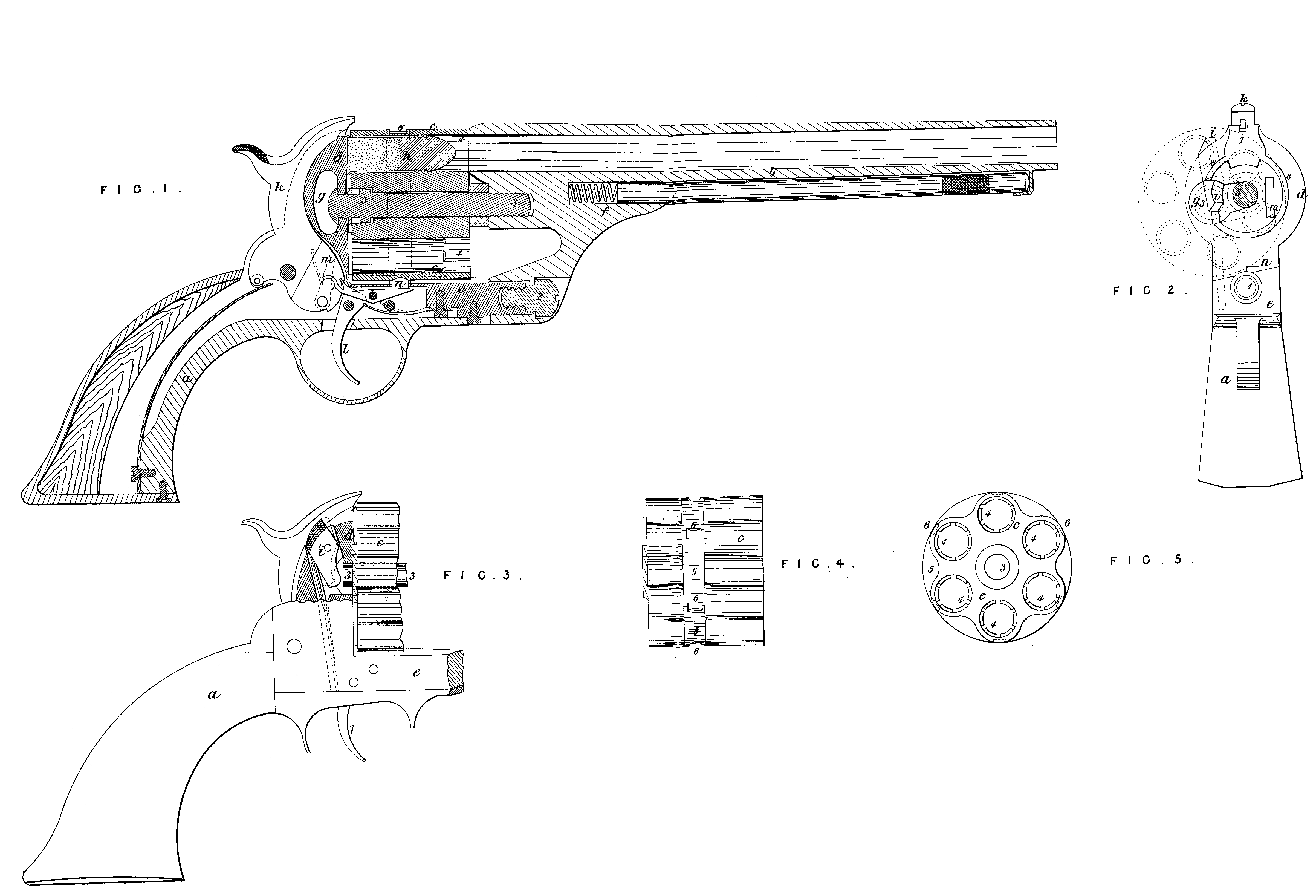
Fig. 1 is a vertical longitudinal section of my improved arm.
2 is an end view with the barrel and cylinder removed, and the center pin on which the chambers revolve in section.
3 is a partial elevation of the handle and chambers.
Fig. 4 is a side view; and
5 is an end view of the chambers. Similar letters refer to the same parts.
My said Invention relates, first, to a means for attaching the stock, barrel, and cylinder, so that said cylinder can be swung aside from the stock for the purpose of loading or removing the charge from the piece, but when in position for firing, said parts are held firmly together. In all the arms of this character. in which a rifled barrel is employed, the ball has been slugged or forced into the rifle grooves in the barrel. The ball as it is discharged from the chamber in line with the barrel meets with the obstruction and comparative detention caused by the said riding, and the recoil of the powder acts to produce an opening between the front end of the chamber and the rear of the barrel, causing escape of gases or “windage.”
My Invention obviates this difficulty, and relates, second, to forming the forward end of each chamber with a rifled surface corresponding to the grooves in the barrel, so that the ball entered with the cartridge is slugged previous to entering the barrel, and the explosion and the detention of the balls in being forced into the rifling cause the chambers to press firmly against the rear end of the barrel, thereby cutting off and preventing as much escape of gas as possible. My revolving breech fire-arm is formed with chambers open at the rear end to receive cartridges with a metallic capsule containing the powder and receiving the ball, a hollow. flanged ring being provided for the fulminating material around the base of the cartridge.
In the Drawing, a is the stock, of any usual size or shape; b is the barrel c is the cylinder of chambers or revolving breeches; d is the metallic breech piece or recoil plate behind the chambers, and e is an arm therefrom beneath. the chamber c to the bracket f on the lower side of the barrel b. These parts e and f are attached to each other by a gudgeon 1 projecting from the former, and passing through a hole in the bracket f, and 2 is a screw securing the barrel and bracket to the arm e. The center pin 3 on which the chamber c revolves is formed as shown in Fig. 1; the forward end of this pin enters the part f below the barrel, where it is secured in place by any competent means, and a shoulder on this pin serves to prevent the chambers disconnecting or sliding off the pin when the barrel is disconnected from the stock. On the rear end of the pin 3 is a collar, by which the stock and barrel are connected; for this purpose I provide a recess in the recoil plate d, as seen at g, in Fig. 1. This recess is formed large enough at one end to pass the said collar, and is undercut or grooved, as seen in Fig. 1, so that when the barrel and stock are in proper line the said recess contains the pin, and the collar on the end thereof is in the space formed behind for the same. It will now be evident that when the barrel and chambers are turned aside on the gudgeon 1 to the position shown by dotted lines in Fig. 2, that some of the chambers are clear of the metallic recoil plate d, and are open from end to end, so that the said chambers can be cleared of the metallic cartridge cases, and new cartridges inserted, and the cylinder can be revolved while in this position, so as to give access to the respective chambers. When turned back to its place the collar on the end of the pin 3 makes a firm connection between said pin and the recoil plate d. To prevent the cylinder and barrel swinging aside when in use, I provide the latch i, which springing against the side of the said pin 3 retains the parts in position for firing. The end of this latch projecting from the metallic breech-piece allows for its being moved by the thumb or finger when the breeches are to be swung aside. k is the hammer for exploding the cartridge, the same being actuated by a suitable mainspring; l is the trigger; m, the pawl for revolving the cylinder of breeches; and n the stop or bolt for holding the respective chambers in line with the barrel. The various parts k, l, m, and n do not form any part of my present Invention, they may therefore be constructed and operate in any well known manner as is usual in this character of fire-arm. The advantages of this means for connecting the barrel and stock will be apparent, for the explosion is sustained by the center pin 3 and gudgeon 1, at the same time free access to the chambers is easily obtained. The forward part of each chamber is bored smaller than the rear, in order that rifle grooves 4, 4, may be cut therein, and for this purpose the rifling instrument may be passed through the barrel b, and applied to rifle each chamber in succession, or otherwise, so that the grooves of the barrel and chambers correspond when in line with each other. The cartridge I employ is provided with a metal shell or case setting at the rear against the recoil plate d, and carrying the ball h at the forward end. This character of cartridge is well known, and it will be evident that either this cartridge or one acting in a similar manner is the only one that can be employed with this improvement, as the chambers have to be open at the rear, in order that the ball may be entered behind the rifling at the forward end. When the piece is discharged, the slugging of the ball is effected in the chamber, the act of doing which tends to force the chamber against the rear end of the barrel, the ball proceeds, and the force of the powder is not decreased by “windage,” as heretofore. The stop lever or bolt n that holds the cylinder in place, as heretofore, takes into the recesses 6 in the surface of the cylinder c, and to ensure the correct action of said lever or bolt, it is important that the said surface be cylindrical at this point, but the weight of the cylinder c is greatly increased by making the entire exterior cylindrical; I therefore recess the metal between the chambers, as seen in Figs. 4 & 5, so as to remove useless weight, and leave a band or ring 5 to receive the said notches 6. The forward part of the recoil plate d is formed with the part 7 and ring 8 as a level surface to take the rear ends of the metallic cartridge cases, while the rest of the surface is slightly sunk down, thereby the cartridge case is fully sustained at the time of explosion by the part 7, and friction is avoided in rotating the chambers c, because the ring 8 against which part of the base of the cartridges bear to keep it in place is comparatively near the center pin 3, whereas if the friction were near the outer edge of said recoil plate d, the power necessary to rotate the chambers c would be increased.
Having thus described my said Invention, what I claim and desire to secure by Letters Patent, is,—
First, the center pin 3, and its collar at the back end, retained within the recess g, combined with the cylinder c and barrel b swinging on the gudgeon 1, in the manner and for the purposes set forth.
Second, I claim the latch i in combination with said center pin 3, to retain the parts in place while the arm is being discharged, as specified.
Third, I claim the employment in a cylinder with chambers open at the rear of rifling at the forward end of the chambers corresponding with the grooves in the barrel, for the purposes and as set forth.
Fourth, I claim the band or ring 5, having the recesses 6, 6, for the stop lever or bolt, the said ring being formed as and for the purposes specified.
Fifth, I claim the recoil plate d, formed with the projecting parts 7 and 8, as and for the purposes specified.
In witness whereof, I, the said Daniel Moore, have hereunto set my hand and seal, this Fourteenth day of January in the year of our Lord One thousand eight hundred and sixty-three.
DANL. MOORE. (L.S.)
Witnesses,
A. J. Bergen,
of Brooklyn, N.Y.
Thog. Geo . Harold,
Brooklyn, N.Y.