US 186509
UNITED STATES PATENT OFFICE.
DANIEL B. WESSON, OF SPRINGFIELD, MASSACHUSETTS.
IMPROVEMENT IN REVOLVING FIRE-ARMS.
Specification forming part of Letters Patent No. 186,509, dated January 23, 1877; application filed December 1, 1876.
To all whom it may concern:
Be it known that I, Daniel B. Wesson, of Springfield, in the State of Massachusetts, have invented a new and useful Improvement in Revolver Fire-Arms; and that the following is a full, clear, and exact description thereof, reference being had to the accompanying drawings, making a part of this specification, and to the letters of reference marked thereon.
My invention relates to that class of revolver fire-arms having a central ejector-stem operating through the cylinder; and it consists in a rocking lifter-catch, secured in a recess by a spring, and operating, in combination with a lifter, to control the movement of the ejector, as will be more fully hereinafter described.
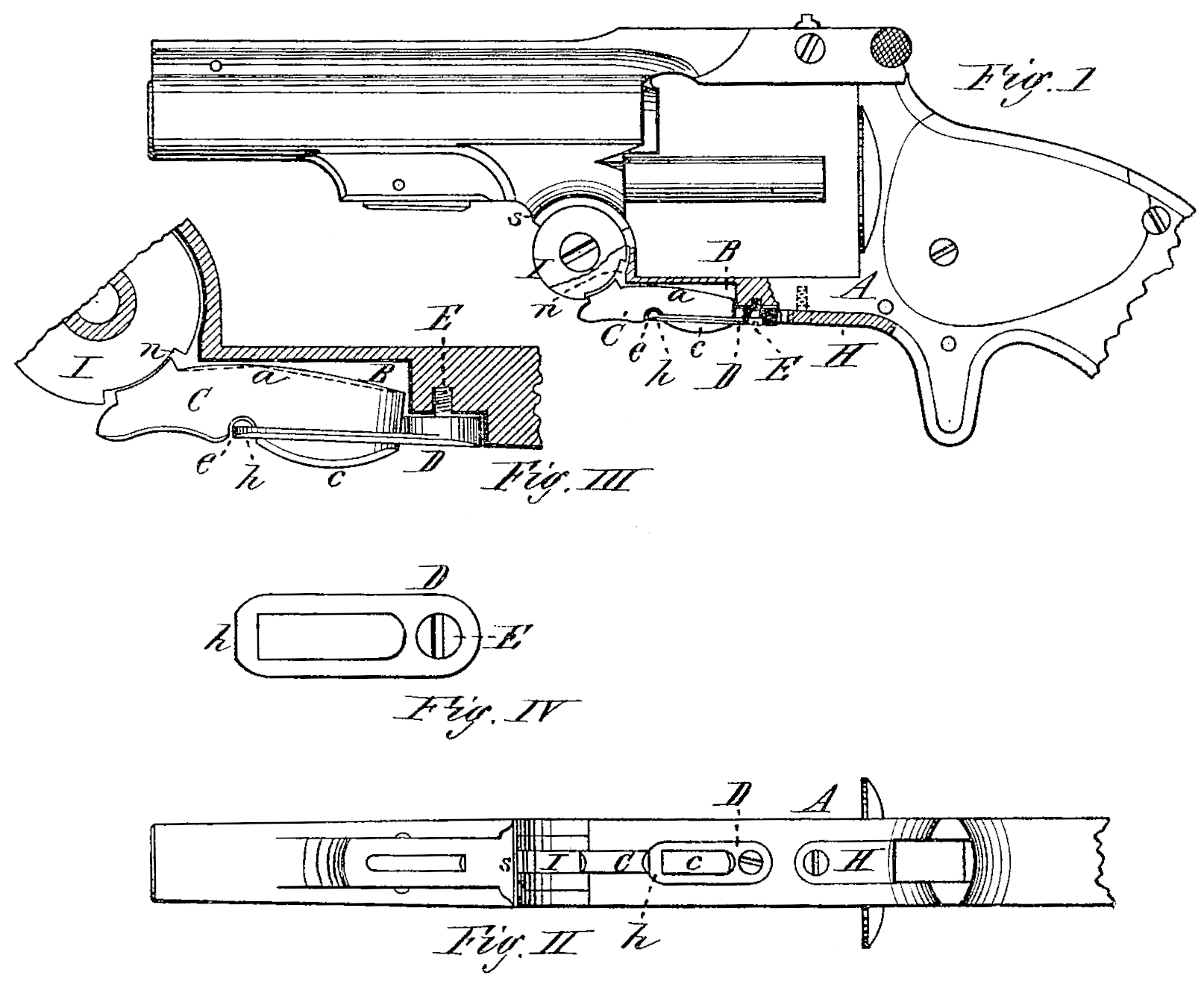
Figure I is a side view of a revolver having my invention applied, with a part of the lower portion of the frame broken away to show the construction. Fig. II is a plan view of the lower side of the arm. Fig. III is a section through the lower forward part of the frame; and Fig. IV is a plan view of the lower side of the lifter-catch spring.
In the drawings, A represents the frame of an ordinary revolving fire-arm of this class, in the forward part of which the lifter I is pivoted to rotate freely, which is provided with the ordinary teeth, to engage with projections upon the ejector-stem, but which are not required to be shown in the drawing. The lifter I is also provided with the recess n, to engage with a catch or projection made upon the forward end of the lifter-catch, in the ordinary manner. The latter, however, I make with the usual projection at the for Ward end, but with its upper side a made on a curve, or in such manner as to rock against the upper side of the recess B, made in the frame; and in the lower side of the catch I make a small recess, e.
The spring D is made sufficiently elastic, and has a slot, F, made therein, having a small bar, h, across its free end, and when the catch O is placed in the recess B the spring is secured to the lower side of the frame, or in a recess made therein, by a screw, E, with the part h of the spring bearing up against the catch C, and with the part c of the latter protruding through the slot F, made in the spring.
The operation of my invention is as follows: When the barrel is unlatched from the frame at the top, and tilted down to throw out the shells, the lifter revolves upon its pivot until the part s, beneath the barrel, strikes against the end of the catch C, be tween it and the lifter I, and forces the catch out of the recess n, and the ejector quickly moves back into place, being actuated by the ordinary spring, the catch C rocking against the upper side of the recess B.
If it is desired to prevent the ejector from being forced out, when the barrel is tilted, the finger is pressed up against the protruding part e, and the catch is rocked, as before, the spring D quickly forcing it back to place, as soon as the pressure of the finger is removed.
In practice, I may prefer to make the spring D as an elongated part of the trigger-plate H, so that when said plate is inserted in place, the whole will be secured by one screw.
It is evident that the upper part of the lifter-catch may be formed by two straight parts meeting at an angle, as shown by dotted lines in Fig. III, without departing in the least from the principle of construction; and it is also evident that either the curved or angular form above described may be given to the upper part of the recess B, and the upper part of the catch be made straight, so that the same rocking movement of the catch would result.
One great advantage of this construction is, that whenever the shells become hard to eject from the chambers from any cause, the whole power applied to eject the shells is brought to bear directly against the end of the catch, and that in turn is forced endwise against the frame, the whole rear end of the catch having a firm bearing against the frame in the operation, which renders the catch much less liable to disarrangement and breakage, and very strong and effective in its action.
Having thus described my invention, what I claim as new is—
The combination of the rocking lifter-catch, spring, and lifter, all constructed and operating substantially as herein described.
DANIEL B. WESSON.
Witnesses:
T. A. Curtis,
G. H. Blandon.

