
US 187689
UNITED STATES PATENT OFFICE.
DANIEL B. WESSON AND JAMES H. BULLARD, OF SPRING FIELD, MASS., ASSIGNORS TO SAID WESSON,
IMPROVEMENT IN REVOLVING FIRE-ARMS.
Specification forming part of Letters Patent No. 18,689, dated February 20, 1877; application filed January 29, 1877.
To all whom it may concern:
Be it known that we, Daniel B. Wesson and James H. Bullard, both of Springfield, in the State of Massachusetts, have invented a new and useful Improvement in Revolving Fire-Arms; and that the following is a full, clear, and exact description thereof, reference being had to the accompanying drawings, making a part of this specification, and to the letters of reference marked thereon.
Our invention relates to that class of revolving fire-arms in which a many-chambered cylinder is used in connection with a single barrel; and it consists, first, of a projection extending down to a point in the rear of the rear face of the cylinder, made upon the latch, which secures the barrel to the frame at the rear end of the barrel; and, second, it consists of a screw-thread and annular recess made upon the central stem upon which the cylinder revolves, in connection with a corresponding screw-thread made in the central hole of the cylinder, by means of which the cylinder is secured upon the central stem or pin upon which it revolves; and, third, it consists of a pawl pivoted in the lifter, by which the ejector is operated to force the shells from the cylinder, all which will be more fully hereinafter described.
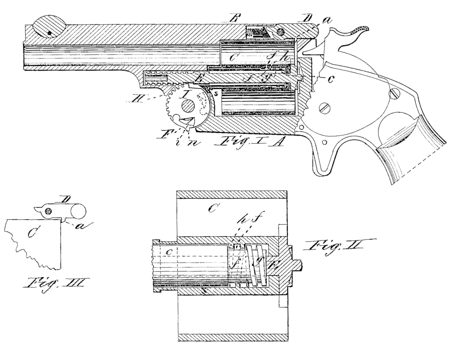
Figure I is a longitudinal vertical section of a revolver made according to our invention. Fig. II is an enlarged sectional view through the central part of the cylinder, showing the screw-threads made in the latter and upon the central stem; and Fig. III is a side view of the latch which secures the rear end of the barrel to the upper part of the frame, showing the projection for preventing the cylinder from moving off its stem.
In the drawings, A represents the frame of a revolving fire-arm, made substantially in the ordinary manner, in the forward part of which is pivoted the lifter I, which is arranged to operate the ejector-stem in forcing the shells from the chambers of the cylinder. The latch D, which is pivoted, as usual, to the rear end of the barrel B, has upon its lower side a projection, a, extending down a short distance to a point in the rear of the cylinder C, and just behind it, when the latter is in place upon its central stem c, and when the latch is raised, as in the ordinary movement of unlatching the barrel from the frame, the projection a is moved upward from its position behind the cylinder, so that the latter may then be removed from the central stem c, if desired.
A screw-thread, h, is made on the inside of the cylinder C, in its central hole, and a corresponding screw-thread, g, is made upon the central stem c, with an annular recess, f, in front of it, so that placing the cylinder upon the stem c, and turning the former until the screw-thread h passes entirely through the thread g upon the stem and into the annular recess f, the cylinder is then free to revolve upon the stem, the screw-thread h of the cylinder revolving around in the annular recess f.
When the cylinder is in place, (the latch D being always down, except for an instant while being unlatched from the frame,) the small projection a on the latch prevents the cylinder from turning off from the stem or being accidentally detached.
The lifter I, which actuates the ejector-stem E, has a recess made therein, in which is pivoted a pawl, F, provided with a small projection, n, and the pawl is held outward by a small spring, i, placed inside the pawl in the recess, so that when the barrel is unlatched from the frame and tilted downward the small projection a strikes against the lower forward end of the frame A, and the lifter I is thereby held stationary or prevented from rotating, and causing the ejector-stem to move through the cylinder and eject the shells; but as the part H in front of the lifter moves around it rides over the projection n, and forces in the swinging end of the pawl, and releases the lifter I from its stationary position, allowing it to rotate when the ejector-stem E is forced in again by its spring. This rotary movement of the lifter I brings the pawl F into the position shown in dotted lines in Fig. I; and when the barrel is tilted up again, the moving part of the arm, forming the joint in which the lifter is pivoted, strikes the projections on the lifter, and moves the latter and the pawl back to their original position, (shown in black lines in Fig. I,) the pawl F being again pressed in during its backward movement by the projection in riding against the curved front end of the frame A in the joint. This pawl may be denominated the “catch”, and by making the lifter I with its catch pivoted therein, the whole operating mechanism is more compact, and the frame. A may be made solid, and therefore much stronger.
It is obvious that it is immaterial as to whether the cylinder oscillates or revolves, so far as the operating mechanism above described is concerned, as it would be equally operative in either case. It is also evident that the annular recess fin front of the screw thread upon the stem c. may be of any desired length, and amount to a reduction in the size of the stem, or a portion of it, and would operate precisely the same provided the screw thread was in rear of it.
Having thus described our invention, what we claim as new is—
1. The combination of the pivoted latch D, provided with the projection a, and the cylinder C, substantially as and for the purpose described.
2. The combination of the cylinder, provided with an internal screw-thread, h, and the stem c, provided with a corresponding screw-thread, g, and recess f, substantially as and for the purpose set forth.
3. The combination of the oscillating or rotating lifter I with its catch F pivoted therein, and operating substantially as and for the purpose described.
DANIEL B, WESSON.
JAMES H. BULLARD.
Witnesses:
G. H. Blanden,
G. D. Chamberlain.