
US 157860
UNITED STATES PATENT OFFICE.
DANIEL MOORE, OF BROOKLYN, NEW YORK, ASSIGNOR TO MERWIN HURLBURT & CO., OF NEW YORK CITY.
IMPROVEMENT IN REVOLVING FIRE-ARMS.
Specification forming part of Letters Patent No. 152,360, dated December 15, 1874; application filed September 12, 1874.
To all whom it may concern:
Be it known that I, Daniel Moore, of the city of Brooklyn, county of Kings and State of New York, have invented an Improvement in Revolving Fire-Arms, reference being had to the accompanying drawings, forming part of this specification, in which—
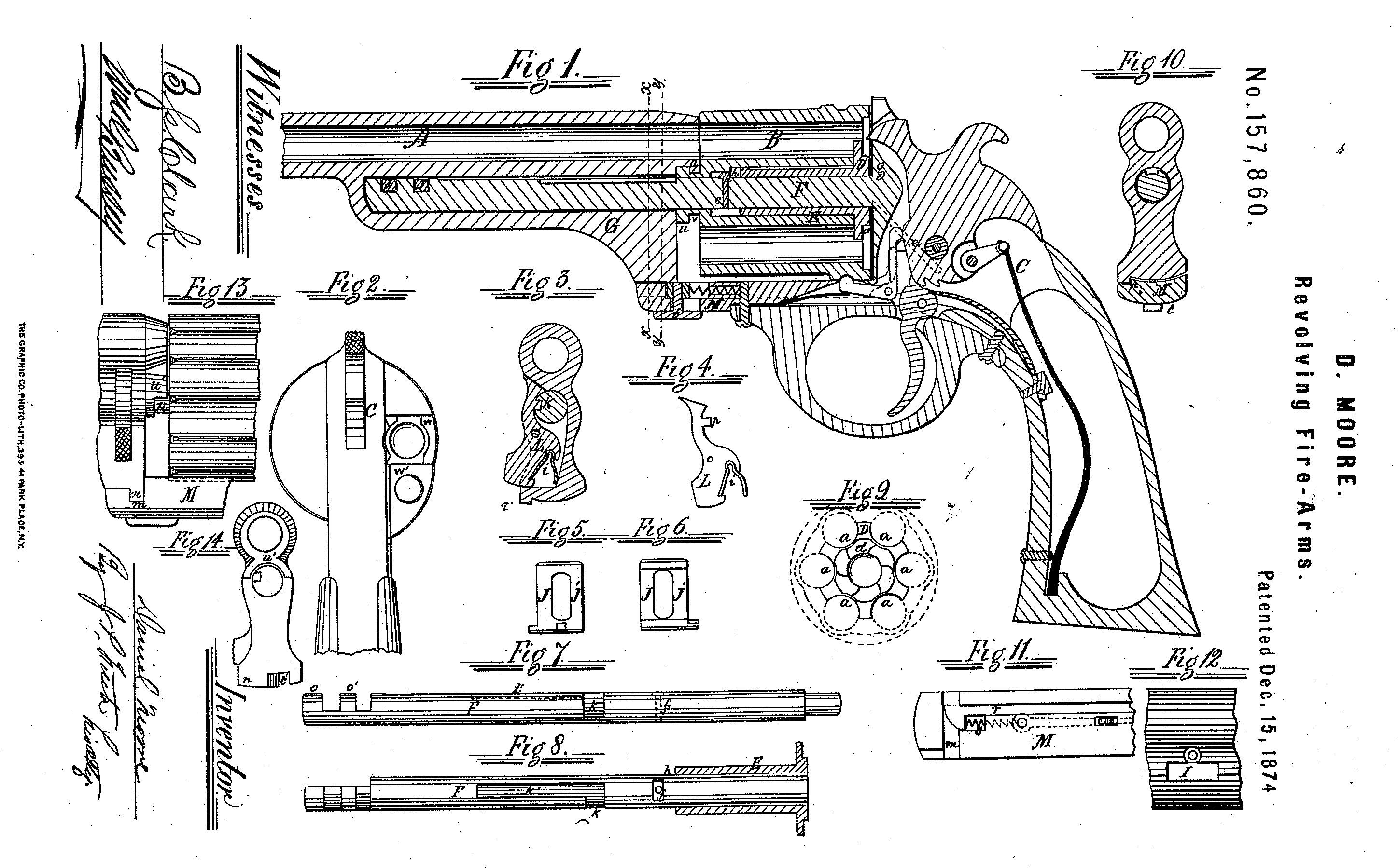
Figure 1 is a vertical central section of a pistol containing my invention, and Fig. 2 is a rear-end view of the same. The other figures are detail views of several of the parts of the pistol, of which Fig. 3 is a cross-section on the line y y, Fig. 1. Fig. 4 is a face view of the spring-stop, by which the barrel in sliding on the center-pin is stopped at a given point. Figs. 5 and 6 are opposite face views of a key employed in locking the barrel on the center pin. Fig. 7 is a side face view of the center-pin attached to the stock on which the cylinder revolves, and by which the barrel is connected with the stock. Fig. 8 is a top face view of the same, with the cartridge-extractor and its sleeve in section. Fig. 9 is a rear face view of the cartridge-extractor, with the end of the cylinder shown by dotted lines. Fig. 10 is a cross-section of the pistol on the line x x, Fig. 1. Fig. 11 is an upper face view of the end of the stock of the frame. Fig. 12 is a side view of a section of the barrel and bracket, showing an opening for the locking-key bolt, Figs. 5 and 6. Fig. 13 is a side view of a broken piece of the rear end of the barrel and bracket and the front end of the cylinder; and Fig. 14 is a rear-end view of the barrel and bracket.
My invention relates to a revolving fire-arm, designed to use metallic-cased cartridges, and in which the cylinder and barrel slide forward on the center-pin to afford opportunity to remove the cartridge-shells after firing; and consists in the combination, with the cylinder and center-pin, of a cartridge-extractor, which, as the cylinder is moved forward on the center-pin, withdraws from it all the cartridge-shells simultaneously, the said extractor having a sufficient longitudinal movement on the said pin to permit the shells, after being so withdrawn, to readily drop out of and away from the pistol; also, in the peculiar combined locking device and gas-check, hereinafter described, by which the barrel is connected to the cylinder; also, in the peculiar devices, hereinafter described, whereby the barrel is connected to the frame, permitting a longitudinal motion of the barrel and cylinder on the center-pin, and yet enabling the barrel to be securely locked to the stock.
A is the barrel; B, the cylinder; and C the frame.
The mechanism of this pistol, (shown in the drawing,) so far as relates to the hammer, trigger, main and rear springs, and the device for locking the cylinder rotarily, do not differ essentially from those now in use; a particular description of the same is therefore unnecessary.
I will confine my description to the parts Which I deem novel.
D is the cartridge-extractor. It consists of a circular plate of metal, which fits into a corresponding circular recess in the rear end of the cylinder B. The peripheral line of this circular plate preferably coincides with a circle drawn through the centers of the several chambers of the cylinder, and semicircular notches at are made in the periphery of the said plate corresponding to the said several chambers; so that when the said plate is in place in the circular recess in the cylinder, and cartridges are inserted in the chambers, a part of the circumference of the cartridges at their bases will lie within the said semicircular notches, and corresponding portions of their projecting heads rest against the outer face of such plate, whereby, when the cylinder is drawn away from the said plate, the latter will act to withdraw the cartridges or their cases from the cylinder. This extractor is attached to a sleeve, E, which fits loosely onto, the center-pin F and enters the cylinder but only a portion of its length, the cylinder, through which passes the center-pin, being bored out to receive the sleeve, forming an annular recess between the center-pin and the cylinder the length of the sleeve or a little longer, and the length of the sleeve is somewhat greater than that of the cartridge, so that when the cartridges are drawn by it entirely from the cylinder, the forward end of the sleeve will still remain in the cylinder. A feather, c, on the sleeve, passes into a slot in the cylinder, thereby securing the rotation of the cylinder with the extractor, and securing the adjustment of the notches to the chambers of the cylinder. On the rear face of the said extractor is the ratchet-wheel or annulus d, which is actuated by the pawl-lever e, (dotted lines,) to revolve the retractor, and with it the cylinder. In the center-pin Fig fixed a stop-pin, f, between which and the end of the sleeve E there is some space, h. This permits a longitudinal movement of the sleeve on the pin, thereby preventing the cartridge-shells, after being withdrawn from the cylinder by sliding the cylinder forward on the center-pin from being retained by their heads binding between the extractor and the recoil-shield g. G is a bracket, made in one piece, solid with the barrel. It is bored nearly through longitudinally, to receive the cylindrical center-pin F. I is a slot or opening through the bracket, to receive the locking key-bolt J. L is a retaining stop, pivoted in an opening in the side of the bracket, and pressed into engagement with the notch or slot k in the center-pin by a spring, i. The said transverse slot k opens into a longitudinal slot, k’, thus permitting the brackets and barrel to be drawn off from the center-pin until the nose n of the catch L, in traversing the said slot k’, is stopped against the end of said slot. Then, if it is desired to remove the barrel entirely from the center-pin, it may be done by pressing upon the lower end of the catch Li, thereby lifting its nose out of the slot. On the end of the center-pin F are formed key-bits o o’, the portion forming the bolts being flattened by the cutting away of about one-half of its diameter, so that it may pass under the key-bolt J, and then, by being turned a quarter around, locked into the bolt J. Near the fore end of the strap M of the frame is a slot, m, across the same, to receive a lip or projection, n, formed on the face of the base of the bracket G. Om one side of this face is also a notch, p, to receive the lip q, to prevent the bracket G from swinging beyond its proper point. In a longitudinal groove in the upper face of the said strap is a sliding catch, r, the beveled end of which is pressed forward into the slot on by a spiral spring, s.
When the bracket is swung to its place over the strap, the lip in presses back the catch against the spring s until the bracket reaches its position and the lip q stops in the notch p, when the said catch, under the stress of said spring, slides forward into a notch, t’, cut across the lip in, and thereby the bracket is securely locked in position. t is a finger – piece, the stem of which is screwed into the said catch r, through a slot in the strap, whereby the said catch may be withdrawn and the bracket unlocked from the strap.
On the forward face of the cylinder is a projecting boss, u, having an annular recess, v, next to the face of the cylinder, and upon the rear end of the barrel is formed a semicircular collar, u’, recessed to receive the projecting rim of the boss u. When the barrel and cylinder are in position on the center-pin, this boss and collar form a lock, by which the cylinder is drawn forward on the pin with the barrel, and also a very good gas-check. Provision is made for loading the cylinder through an opening, w, in the recoil-shield, covered by a slide, w’, in the usual way.
After firing this arm, the empty shells are removed as follows: The catch r is withdrawn from the notch t’ by sliding back the finger-piece t, thereby unlocking the bracket G from the strap M. The bracket and barrel are then revolved a quarter round upon the center-pin, and slid forward upon it, carrying the cylinder with them until stopped by the spring – catch L, the nose of which will have reached the end of the slot k’. The extractor, by this movement, has been carried along with the cylinder until the sleeve E reaches the pin f, when it will stop, and there holding the empty shells, cause them to be withdrawn from the cylinder; and, the extractor being carried a little distance away from the recoil-shield, thus obviating the binding of the flanged head of the shells between the same, the shells will readily fall out. By reversing these motions the barrel and cylinder are carried back to their first position, and there locked in place. If it is desired to remove the barrel and cylinder entirely from the center-pin, it may be done by pressing upon the spring-catch I, thus lifting its nose out of the slot k’.
When the parts are in position, as represented in Fig. 1, the bracket is locked onto the center-pin not merely by the catch L, which, being a spring-catch, might not be secure, but also by the key-bolt J, the key-bits o o’ being then turned into the wards of the said bolt.
I would recommend the use of the bolt J separate from the barrel; but, if preferred, projections one or more may be formed on the under side of the barrel corresponding in form and position to the body of the bolt when in place, the nose of the front end of the bracket being cut away for the purpose, and the space thereby exposed capped by a separate piece screwed on.
What I claim as my invention is—
1. The combination, in a revolving fire-arm, of the center-pin F, provided with the transverse and longitudinal slots k and k’, the spring-catch L, and the bracket G, as and for the purpose specified.
2. The combination, in a revolving fire-arm, of the center-pin F, the stop-pin f, the sleeve E, extractor D, and cylinder B, in which the extractor is permitted to move a little distance forward on the center pin, away from the recoil-shields, in the act of withdrawing the cartridge-shells, as and for the purpose specified.
3. The combination, in a revolving fire-arm, of the bracket G and the barrel A with the center-pin F, provided with the flattened key-bits o o’ and the key-bolt J, as and for the purpose specified.
Witness my hand this 9th day of September, 1874.
DANL. MOORE.
Witnesses:
William Stevenson,
B. S. Clark.