
US 190240
UNITED STATES PATENT OFFICE
DANIEL MOORE, OF BROOKLYN, ASSIGNOR TO MERWIN, HULBERT & Co., OF NEW YORK, N.Y.
Specification forming part of Letters Patent No. 90,240, dated May 1, 1877; application filed February 19, 1877.
To all whom it may concern:
Be it known that I, DANIEL MOORE, of Brooklyn, in the county of Kings and State of New York, have invented certain new and useful improvements in Revolving Fire-Arms; and I do hereby declare that the following is a full, clear, and exact description thereof, which Will enable others skilled in the art to which it appertains to make and use the same, reference being had to the accompanying drawings, and to the letters of reference drawings, and to the letters of reference specification.
My invention relates to that class of breech-loading revolving fire-arms in which the barrel is hinged to a strap or bracket of the frame, and the cartridges extracted by the forward movement of the cylinder, the heads of the cartridge-shells being held by an annular extractor projecting from the recoil-shield; I and the nature of my invention consists in so connecting the hinged barrel and the rotating cylinder that by turning the barrel on its hinge the cylinder will simultaneously there with be caused to move forward on its axial pin, as Will be hereinafter more fully set forth.
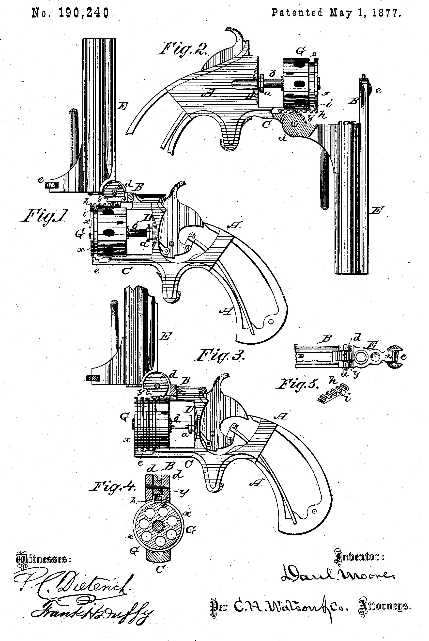
In the annexed drawing, Figure 1 is a side view of a revolving fire-arm embodying my invention, in which the barrel is hinged to a strap or bracket above the cylinder. Fig. 2 is a similar view, showing the barrel hinged to a strap or bracket below the cylinder. Fig. 3 shows a modification of my invention, and Figs. 4 and 5 are detailed views of parts thereof.
A represents the frame of a breech-loading revolving fire-arm, with top and bottom projecting straps or brackets B and C, respectively, and with the recoil-shield D, from which latter projects the annular extractor a and the axial or center pin b.
E is the barrel, provided at its rear end, on the top, with a lug or projection, d, which is pivoted in a slot in the end of the upper strap or bracket B. The barrel is locked to the lower strap C by the usual spring-catch e.
G represents the many-chambered revolving cylinder, placed on the axial or center pin b, and constructed in the usual manner for this class of fire-arms, and it has near its front end, in its outer surface, a circumferential groove, x, as shown.
On the lug or projection d of the barrel E. is formed a series of cogs, y, which take into and operate a rack-bar, h, placed in a groove in the under side of the upper strap B. On the under side of the rack-bar h, near the front end, is a lug, i, which enters the groove a on the cylinder G.
By this construction of mechanism it will be seen that by breaking the joint or turning the barrel on its hinge the cylinder is thereby, and simultaneously there with, moved for Ward on the axial pin away from the recoil-shield.
The object of this invention is to release the cylinder from the cartridge-shells and allow them to fall from the chambers, as the heads of the cartridge-shells are held by the extractor a, and the cylinder started forward simultaneously with and by the breaking of the joint of the barrel.
This may be accomplished by various other mechanical means—as, for instance, the barrel may be hinged to the lower strap C, and break downward, when the rack-bar h will be placed in a groove in the upper face of said lower strap, as shown in Fig. 2; or, in place of said rack-bar, the forward end of the cylinder may be formed with a series of circumferential grooves, ac, into which the cogs y on the lug d will take to move the cylinder forward, as shown in Fig. 3.
Having thus fully described my invention, what I claim as new, and desire to secure by Letters Patent, is—
1. In a breech-loading revolving fire-arm, the hinged barrel E, having the lug d, that forms part of the hinge, provided with a series of cogs, y, for operating the revolving cylinder longitudinally, substantially as and for the purposes herein set forth.
2. The many-chambered revolving cylinder G, provided with a rack, in combination with the hinged barrel E, having lug d and cogs y, substantially as and for the purpose set forth.
In testimony that I claim the foregoing as my own I affix my signature in presence of two witnesses.
DANL, MOORE.
Witnesses:
Frank Galt,
Wm. B. Upperman.