US 144815
UNITED STATES PATENT OFFICE.
DAVID WILLIAMSON, OF GREENVILLE, NEW JERSEY.
IMPROVEMENT IN REVOLVING FIRE-ARMS.
Specification forming part of Letters Patent No. 144S15, dated November 18, 1873; application filed November 12, 1873.
Case B.
To all whom it may concern:
Be it known that I, David Williamson, of Greenville, in the county of Hudson and State of New Jersey, have invented certain new and useful Improvements in Revolving Fire-Arms; and I do hereby declare that the following is a full, clear, and exact description thereof, that will enable others skilled in the art to which it appertains to make and use the same, reference being had to the accompanying drawings, and to the letters of reference marked thereon, Which form a part of this specification, in which—
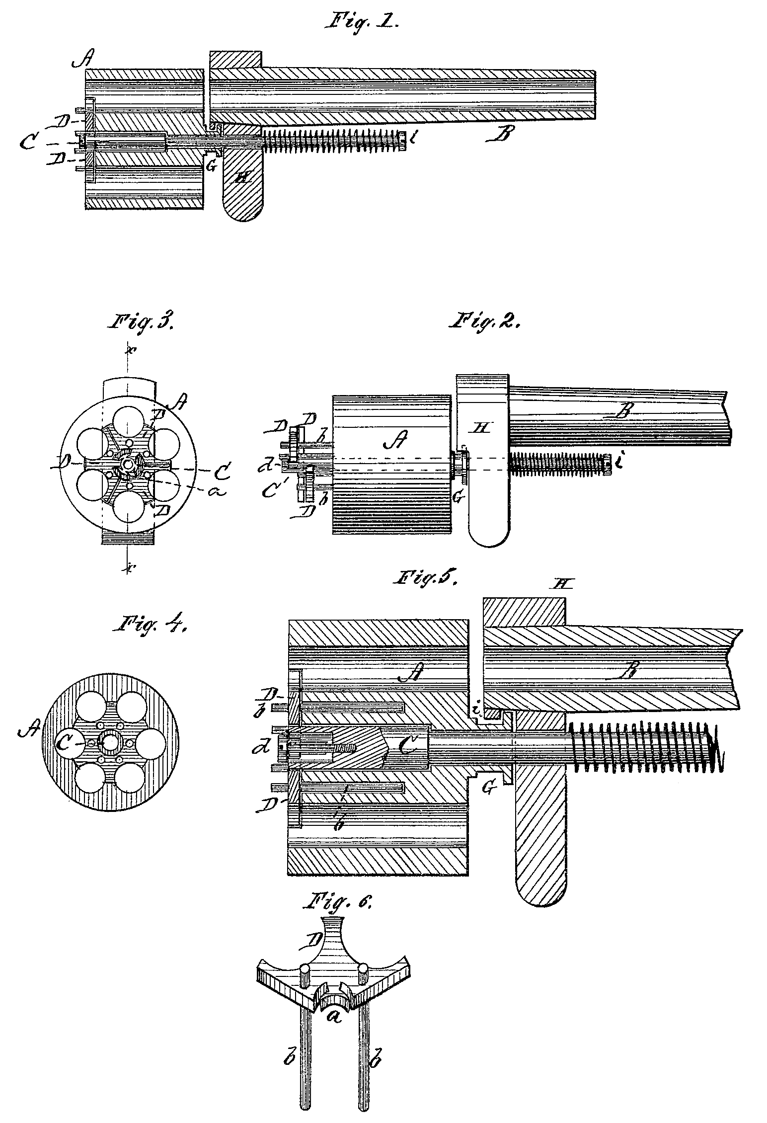
Figure 1 is a longitudinal section of so much of a revolving fire-arm as will illustrate my invention. Fig. 2 is a side view of the same, showing the cartridge-extractor thrown out. Fig. 3 is a rear end view of the cylinder with the extractor in place. Fig. 4 is a transverse Section of the cylinder. Fig. 5 is an enlarged longitudinal section of the cylinder and part of the barrel; and Fig. 6 is an enlarged perspective view of one of the sections of which the extractor is composed.
My present invention is intended as an improvement upon the Letters Patent No. 137,043, for revolving fire-arm granted to me March 18, 1873; and the nature of my invention consists in a cartridge-extractor made in sections, which are thrown out one after the other to act successively upon the cartridges, moving or starting one or more at a time, thereby preventing any great strain upon the pivot-pin, or any other part of the mechanism.
In the accompanying drawing, A represents the many-chambered cylinder, and B the barrel, of a revolving fire-arm, constructed in any of the known and usual ways. C represents extractor-spindle, which may be operated by any desired means and in any suitable manner. The rear end of this spindle C is made tubular, as shown particularly in Fig. 5, and from the end of this tube, inward or forward, are made a series of longitudinal slots of unequal length. DD represent the sections of the extractor-head, which fit in a recess made in the rear end of the cylinder A, and when placed together in position form a whole extractor of the usual shape. Each section D is made rounded at its inner edge to correspond with the exterior surface of the tubular extractor spindle C, and is provided with a T-shaped or similarly-shaped projection, a, to fit in the slot of the extractor-spindle, the shank of said projection passing through the slot, and the head projecting within the tubular end of the spindle. Each section D is further provided with one or more guide-pins, b, passing through holes in the cylinder. When the spindle C is moved to the rear, that section of the extractor which has its projection a in the shortest slot will start first, then the one having its projection in the next shortest slot, and so on to the last section. By this means the cartridges are acted upon in succession, and not all at one time, thereby relieving the strain on the pivot-pill and other parts of the mechanism. The ex tractor may be made in as many sections as desired, so as to have each section act upon one cartridge only, or on more, as may be most convenient. The sections D D are prevented from slipping out from the spindle by means of a screw, d, screwed into the end of the same. The inner portion of the cylinder A extends forward beyond the chambers, and is formed in a collar, G, having a recess, in which the lug i on the barrel-bracket H fits, thus holding the cylinder in position, at the same time allowing it to be revolved in the usual manner. This method of holding the cylinder in position combines simplicity in construction and convenience in removing the cylinder when desired, as the lug i and collar G. govern the longitudinal motion of the cylinder only, and the lug i being on the upper inside of the bracket H, thus allowing the cylinder to drop out by simply removing the spindle C.
The parts may all be separated by simply removing the screw i in the forward end of the spindle C, thus forming a device simple in construction, efficient and effective in operation, not liable to get out of order, and durable in use.
Having thus fully described my invention, what I claim as new, and desire to secure by Letters Patent, is—
1. A cartridge-extractor for revolving fire arms, made in sections, and the sections operating successively, substantially as and for the purposes herein set forth.
2. The cartridge-extractor sections D D, provided with projections a a, of T or other suit able shape, in combination with the tubular end of the extractor-spindle C, provided with longitudinal slots of unequal length, substantially as and for the purposes herein set forth.
In testimony that I claim the foregoing I have hereunto set my hand.
DAVID WILLIAMSON.
Marselus Wauters,
Harry C. Scott.

