
US 279197
UNITED STATES PATENT OFFICE.
DEXTER SMITH, OF SPRINGFIELD, MASSACHUSETTS.
REVOLVER.
SPECIFICATION forming part of Letters Patent No. 279,197, dated June 12, 1883.
Application filed May 8, 1883. (No model.)
To all whom it may concern:
Be it known that I, DEXTER SMITH, a citizen of the United States, residing at Springfield, in the county of Hampden and State of Massachusetts, have invented new and useful Improvements in Revolving Fire-Arms, of which the following is a specification.
This invention relates to improvements in the details of the construction of revolving fire-arms, and is in the nature of an improvement upon my patent of December 13, 1881, No. 9,965, to which reference may be had, the object being to combine the barrel, cylinder, and extracting mechanism shown in said patent, or substantially that, with the frame of the arm in an improved manner, whereby said extractor mechanism may be operated while holding the arm in the position in which it is fired, instead of having to reverse it, as in said patent, and whereby the arm is brought to such a position that said extractor mechanism is more conveniently operated.
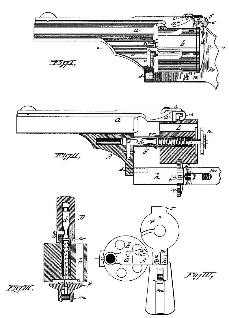
In the drawings forming part of this specification, Figure 1 is a side elevation of a portion of a revolving fire-arm embodying my improvements. Fig. 2 is a plan view, partly in section, of a portion of the arm, showing the parts thereof in a position to operate the extracting mechanism. Fig. 3 is a section on the line x x, Fig. 1. Fig. 4 is a front end view, showing the cylinder swung away from before the recoil-plate.
In the drawings, a is the barrel of the arm, having thereunder the boss D, and having an arm, a2, thereon, extending over the top of the cylinder b, and provided with a hook, e, which engages with a projection, o, on the frame m, above the recoil-plate x. A stop-catch, c, is hung near the end of arm a2, and projects sufficiently above the latter to form a rear sight for the arm. Said catch c is pivoted in arm a2, and has a nose thereon, as shown, which passes through said arm into the space within hook e, and is adapted to engage with a socket, v, in the end of the projection o when the cylinder is locked in the frame.
An arm, h, on the frame m extends forward under the cylinder b, and to the end thereof is pivoted the barrel a, and the parts directly connected with or attached thereto, by a pin or screw, s, which passes through the end of boss D and into the end of arm h.
The construction of the base-pin y, cylinder b, with its neck, and the bead w, the extractor n, with its stem d, and its spring, is substantially like the similar parts of the arm shown in my said patent.
The catch z in this arm is differently constructed from the “catch d” in said patent, in that its engaging-points act against the sides of the extractor-stem and the neck on the cylinder, instead of under them.
The operation of my improvements is as follows: To load the arm the end of the catch c is borne down, lifting its nose out of the socket v, and arm a2 is pushed to the right, swinging the barrel and cylinder on the end of arm h over sidewise, as in Figs. 2 and 4, carrying the rear end of the cylinder clear of the recoil-plate x. The cartridges may then be inserted into the cylinder from the rear, and the latter and the barrel are then swung back to the position shown in Fig. 1, catch c there firmly locking them, and the arm is ready to be fired. After the cartridges have been discharged the barrel and cylinder are swung off to one side, as before, the cylinder is drawn back, as in Fig. 2, pulling the stem d out until the forward catch on z engages in the groove therein, when it is suddenly moved forward away from the extractor n, whereby the cartridge-shells are extracted from the cylinder. The forward movement of the cylinder is continued, carrying the bead or rim w on the neck of the cylinder under the catch z, lifting it out from the groove in stem d, and allowing the extractor-spring to operate and force the stem back to the position it occupied before the cylinder was drawn back, as shown in Fig. 2. The arm may then be reloaded, as before described, and shut.
What I claim as my invention is–
1. The combination, with the frame of a revolving fire-arm, having an arm, h, extending forward, of a barrel pivoted to the end of said arm, and having the arm a2 thereon extending over the cylinder, and engaging by a lateral motion with the frame over the recoil-plate, and carrying upon its base-pin a cylinder and shell-extracting devices, substantially as described, adapted to swing on its pivot in the direction of the plane of the face of the recoil plate, to carry the cylinder beyond the latter and permit it to have a reciprocating motion upon said base-pin rearwardly beyond said recoil-plate.
2. The combination, with the frame of a revolving fire-arm, of a barrel pivoted on said frame carrying a cylinder and shell-extracting devices, substantially as described, adapted to be operated by moving the cylinder reciprocatingly on its base-pin, capable of being swung on its pivot to move the cylinder to one side in a line with the face of the recoil-plate, to permit the cylinder to have a reciprocating motion rearwardly beyond said plate.
3. The combination, with the frame and barrel of a revolving fire-arm, of a cylinder and shell-extracting devices, substantially as described, adapted to be swung to one side in the direction of the plane of the face of the recoil-plate, beyond the latter, to permit the cylinder to have a reciprocating motion rearwardly beyond said plate.
DEXTER SMITH.
Witnesses:
H. A. CHAPIN,
C. J. BARNARD.