
US 269890
UNITED STATES PATENT OFFICE.
DONALD D. SMITH, OF SPRINGFIELD, MASSACHUSETTS.
REVOLVING FIRE-ARM.
SPECIFICATION forming part of Letters Patent No. 269,890, dated January 2, 1883.
Application filed August 16, 1882. (No model.)
To all whom it may concern:
Be it known that I, DONALD D. SMITH, of Springfield, in the county of Hampden and State of Massachusetts, have invented a new and useful Improvement in Revolving Fire-Arms, of which the following is a specification and description.
The object of my invention is to provide a cheap and effective means for locking the barrel of a revolving fire-arm to the frame; and I accomplish this by the mechanism substantially as hereinafter described, and illustrated . in the accompanying drawings, in which—
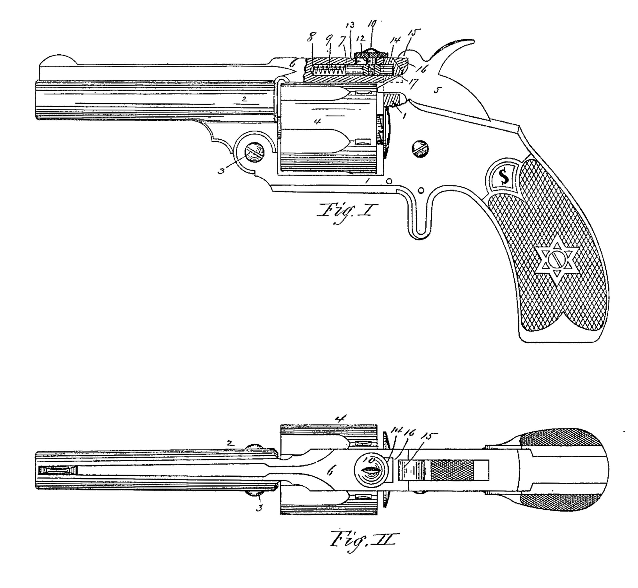
Figure I is a side view of a revolving fire-arm, showing the locking mechanism which secures the barrel to the frame in vertical section on a vertical plane at the axis of the barrel; and Fig. II is a plan view of the same.
In the drawings, 1 represents the frame of a revolving firearm; 2, the barrel hinged to the frame at 3; and 4 represents the chambered cylinder, above which is the strap, as 6, extending rearward from the upper portion of the barrel with a vertical hole or mortise, as 16, in the rear end of said. strap to receive the upwardly-projecting catch, as 14, made on the upper part of the frame 1. A longitudinal hole, as 8, is made in the strap 6 from its rear end, and also a short longitudinal vertical slot, as 13, is made in the upper side of the strap, extending through into the hole, as 8, and a small hole, as 17, is made in the front side of the catch 14 directly in line with the hole 8 in the strap. A small bolt, as 7, is inserted into the hole 8 with a small actuating-spring, as 9, inside, and a threaded hole is made in the bolt 7 in the direction of its diameter, into which is turned firmly up against its shoulder 12 the threaded shank of a button, as 10, the distance between the shoulder 12 of the button and its head being such as to permit the bolt and button to slide freely to and fro. The spring, as 9, always forces the bolt, with its button, as 10, into its most rearward position, and when the strap is forced down upon the frame into the position shown in Fig. I, the bolt, as 7, is quickly moved back, with its rear end projecting into the bole in the catch 14 on the frame, and when in this position the rear end of the strap 6, directly in rear of the vertical catch 14 of the frame, securely holds the barrel in position when the arm is discharged. A short cap, as 15, is made upon the upper part of the hammer, which cap, when the hammer is down in position to explode the cartridge, projects forward a little over the extreme rear end of the strap, as 6, so that at the instant the arm is discharged the position of the hammer and its projecting cap operates to prevent the strap from rising should it by any chance happen to remain unlocked by the bolt 7 at the instant of the explosion.
To unlock the barrel from the frame to insert the charges in the chambers of the cylinder or for any other purpose, it is only necessary to push the button forward toward the barrel and bring the hammer to a half-cock, by which the cap, as 15, on the hammer will be drawn back from its position above the rear end of the strap, and the front end of the barrel is tilted down to expose the rear end of the chambered cylinder. By tilting the forward end of the barrel upward with a quick movement, the barrel is locked firmly to the frame.
Having thus described my invention, what I claim as new is—
1. The combination, in a revolving fire-arm, of a top strap connecting the barrel with the frame in rear of the cylinder, and provided with a longitudinal cavity and a vertical slot or opening above said cavity, a sliding bolt actuated rearward in said cavity by a spring, a button whose shank extends down through said slot and into said bolt, a catch projecting upward from the frame in rear of the cylinder to engage in a hole in said strap, and provided with a hole to receive the rear end of said bolt, substantially as described.
2. The combination, in a revolving fire-arm, of an upwardly-projecting catch made upon the frame in rear of the cylinder, a top strap connecting the barrel with the frame and provided with a longitudinally-sliding bolt and actuating-spring, an operating-button projecting through the top of the strap, and with a vertical hole through the rear end of the strap to receive said upwardly-projecting catch, and a hammer provided with a cap extending forward over the rear end of said top strap, all substantially as and for the purpose set forth.
DONALD D. SMITH.
Witnesses:
T. A. CURTIS,
CHAS. H. WOOD.