
US 516476
UNITED STATES PATENT OFFICE.
ELBERT M. COUCH, OF NORTHAMPTON, MASSACHUSETTS.
CYLINDER-ACTUATING MECHANISM FOR REVOLVERS.
SPECIFICATION forming part of Letters Patent No. 516,476, dated March 13, 1894.
Application filed December 20, 1893. Serial No. 494,144. (No model.)
To all whom it may concern:
Be it known that I, ELBERT M. COUCH, a citizen of the United States, residing at Northampton, in the county of Hampshire and State of Massachusetts, have invented new and useful Improvements in Revolving Firearms, of which the following is a specification.
This invention relates to a certain type of revolving fire-arm in which the cylinder, or revolving magazine, is contained within a flat, circular casing which has the barrel-extension, the said easing being grasped within the hand, it, practically, constituting the stock of the arm, and having at its rear a lever, or trigger, to be borne upon by the ball of the hand, which lever actuates the magazine and lock mechanism.
The object of this invention is to particularly improve the construction of the revoluble magazine and the device which imparts its movement, whereby, in being brought around so that one of its chambers is in line with the barrel, the registry will be positive and accurate. Furthermore, by the exercise of this invention the magazine actuating device is more durable and less liable to become impaired by reason of the action of the recoil in the discharge of the fire-arm.
The improvements are illustrated in the accompanying drawings in which—
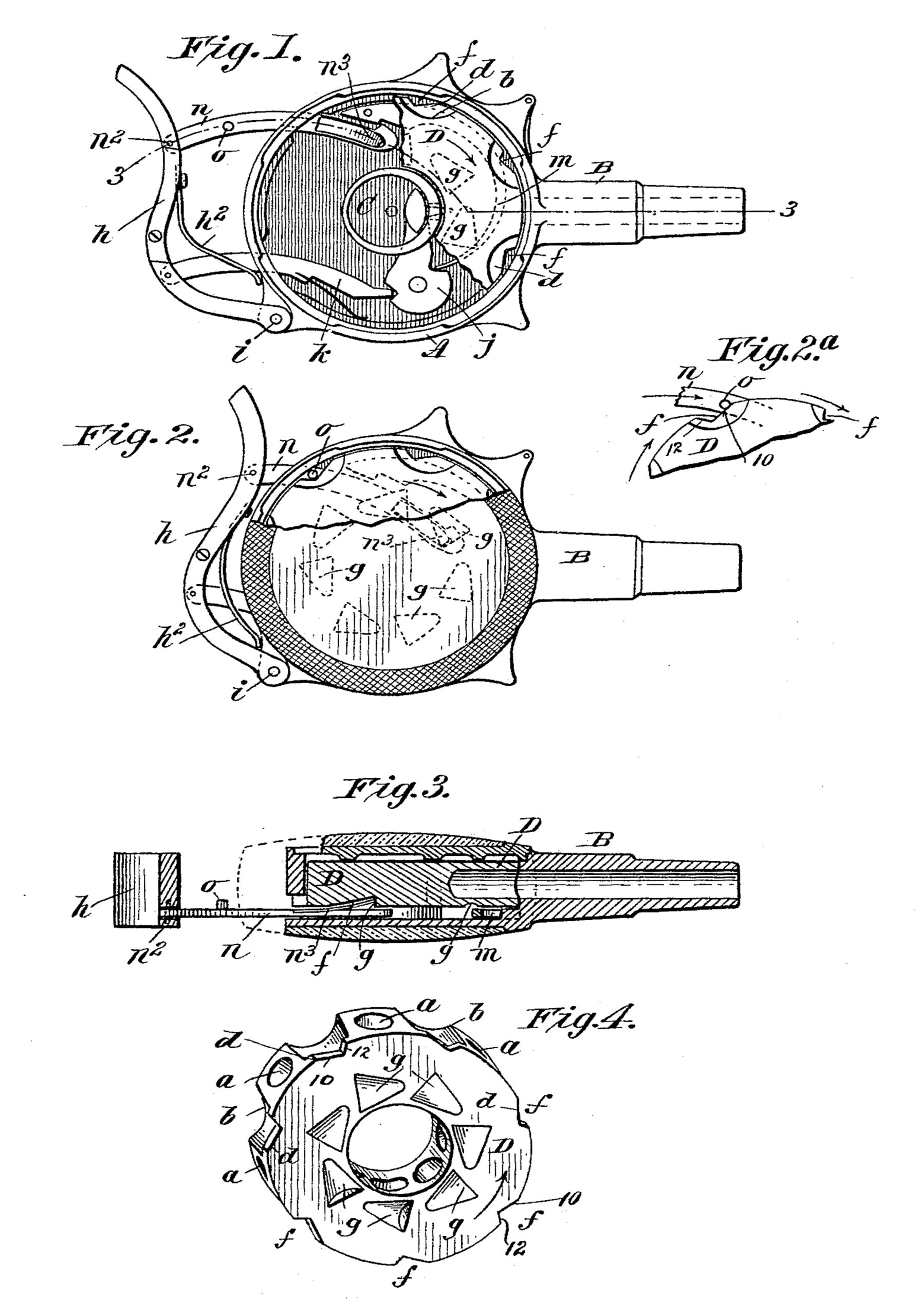
Figure 1 is a face view of the fire-arm with the cap removed, showing, also, a portion of the magazine or cylinder broken away, and representing the operative parts as in their normal positions. Fig. 2 is a face view of the arm showing the actuating parts as in their positions to which they are moved for the discharge of the arm, a part of the outer cap being broken away to more particularly show the relations of one of the notches of the cylinder with a stud upon the cylinder-propelling pawl-arm. Fig. 2a is a view of certain of the parts shown in Fig. 2 as in slightly different operative relations, as hereinafter referred to. Fig. 3 is a sectional view which is understood as taken about on the line 3—3, Fig. 1. Fig. 4 is a perspective view of the cylinder, this view particularly showing the formation of the edge-notches.
In the drawings, the flat, cylindrical, boxlike casing, A, is shown as provided with the extended barrel, B, and the central, hollow hub, C, which constitutes the resistance piece,
or breech-block for the cylinder, D, which has the central opening and fits for rotation about the said part, C. The cylinder has the radial chambers, a, extending, as usual in this type of fire-arm, radially from its inner to its outer peripheries, and intermediate of the ends of the chambers, a, the edge of the cylinder has the series of approximately semi-circular depressions, b, which extend from the upper, or outer, face of the cylinder nearly, but not quite, to the opposite face, thereby leaving a thin web, d, of metal, within each of which is formed an edgewise opening notch, f, with the angular boundaries thereof of unequal lengths. The cylinder also has the recesses, or notches, g, g, upon its under side, as has heretofore been common.
h, is the part which constitutes the trigger, the same being in the form of a compound curved lever, which is pivoted at i, to the rear edge of the casing, A, this trigger having the retracting spring, h2
j is the hammer having its striking point normally disposed within, and adapted to strike the cartridge in one of the cylinder chambers through a perforation in the wall of the breech-block boss, C.
m is the main spring operatively applied to the hammer, and k, is a bar or pawl which is pivoted to the trigger and engages the hammer to throw it back, as the trigger is pressed forwardly toward the edge of the casing, A. The hammer and its actuating device constitute no part of this invention.
n is a bar, or pawl, which, by its rear end, is pivoted as at n2, to the trigger-lever, h,and it projects through an aperture in the edge wall of the casing, A, and has, as the trigger is pressed, a sliding movement along the inner face of the bottom of the casing, the upturned, spring-like member, n3, near its extremity, engaging in one of the recesses, g, to force the cylinder around in the usual manner. This pawl-bar, n, also has the short, rigidly affixed stud, o, at a little distance in advance of the connection, n2, the arrangement of which,—regarded in conjunction with the extent of forcing movement of the cylinder around by the pawl-bar, n and also in conjunction with the shape and arrangement of the adjacent cylinder notch, f—is such as to insure, toward the: completion of the intermittent rotational movement of the cylinder, when it approaches its chamber registry with the barrel-bore, a forcing contact of the stud, o, against the outer part of the long-inclined side, 10, of the adjacent notch, f, (see Fig 2a) whereby the completion of the movement of the cylinder in coming to registry is caused through the medium of the said stud, working upon the said inclined side, 10; and this — final movement to registry is,—by reason of the peculiar forcing impingement of the stud, o, against the lone side of the notch,—at a rate slightly faster than the movement of the forward end spring, n3, of the pawl-bar, n, so that the cylinder “runs away” from the part, n3, so to speak. This action may readily be insured, care being taken to so form the inclined side, 10, that the stud, o, in following its given direction of movement there against, will have not altogether a straightway forcing action, but also something of a cam-like action for the desired gain in speed of the cylinder over the inner end of the pawl-bar, n. The other boundary, 12, of each of the notches f, is at, or nearly at, right angles to the notch-side 10, whereby, as plain, when the side, 10, has exerted its sufficient forcing action to bring the cylinder to register in a positive and efficient manner, said side, 12, of the notch, will by being brought against the stud o positively hold the cylinder against any further and undue rotational movement, until after the discharge of the arm when, on allowing the rearward movement of the spring-pressed part, h, the pawl bar, n, may be retracted to take into the next rearward notch, g, to the one which had been engaged, where upon the actions desired may be again repeated. This form of marginal notch for the cylinder is found to be a great practical improvement over the semi-circular marginal notches formerly provided in the corresponding portions of the cylinder.
Having thus described my invention, what I claim, and desire to secure by Letters Patent, is—
1. In a fire-arm, the combination with this rotatable cylinder having on its face the notches, g, and having on its edge a corresponding series of notches the sides of which are angular to each other, of a reciprocatory bar having a part at or near its inner end to engage said notches, g, and a stud or projection to the rear of its inner end to be brought to a forcing impingement against one of the inclined sides of an adjacent edgewise notch of the cylinder, and means for imparting the reciprocatory movement to the said reciprocatory bar, substantially as described.
2. In a revolving fire-arm, the combination with the barrel and rotatable cylinder having the series of notches, g, on its face and having at its edge the corresponding series of angular notches, of the reciprocatory pawl-bar, n, which is adapted to engage in the notches, g, for forcing the cylinder around and which is provided with the stud, o, to have an intercepting engagement in one of the angular edge notches as the cylinder comes to firing registry with the barrel, and means for imparting the reciprocatory movement of the pawl bar, substantially as described.
3. In a revolving fire-arm, the combination with the rotary magazine, or cylinder,—the chambers of which register with the barrel,— having the series of notches, each with a long inclined side, 10, and an angularly arranged side, 12, and the actuating bar, n, with the projection, o, operating on the long incline to force the cylinder to registry and then engaging with the short inclined side of the notch to prevent further motion of the cylinder, substantially as described.
ELBERT M. COUCH.
Witnesses:
WM. S. BELLOWS,
K. I. CLEMONS.