
USA 17382
UNITED STATES PATENT OFFICE.
EDWARD LINDNER, OF NEW YORK, N.Y.
IMPROVEMENT IN FIRE-ARMS.
Specification forming part of Letters Patent No. 17,382, dated May 26, 1857.
To all whom it may concern:
Be it known that I, Edward Lindner, of New York, in the county and State of New York, have invented certain new and useful Improvements in Fire-Arms; and I hereby declare that the following is a full, clear, and exact description thereof, reference being had to the accompanying drawings, in which—
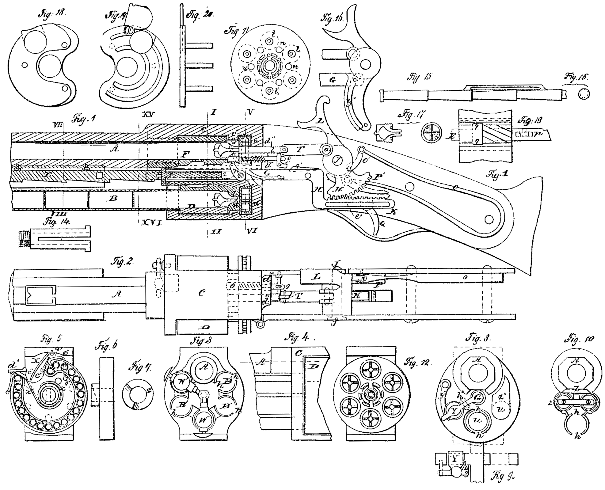
Figures 1,2,3,4,5,6,7,8,9, 10, &c., represent elevations, sections, and plan views of my improvement.
Figs, 1 and 2 show the internal construction of a magazine repeating-gun, having below the barrel an extra-charge barrel, which, according to its length, contains from thirty to fifty cartridges. Between the gun and charge-barrel is a rack, in connection with a piston or slide, which acts upon the cartridges, a Lad which rack is again in connection with the gun-lock, in such a manner that each time the gun is fired off one of the cartridges is forced into a revolving breech-piece, by which means the whole amount of cartridges contained in the charge-barrel can be fired off in the shortest possible time.
The revolving breech-piece is each time, When the gun is cocked, one-sixth part turned round by a mechanism applied at the inside of the same. The percussion-caps are by an arrangement of springs brought exactly opposite the nipple, and are put on the same by the hammer itself at the moment the gun is fired off, while the exploded cap is thrown off from the nipple when the gun is cocked.
As the barrel of the gun, which is at its after end screwed to the frame in such a manner that its bore corresponds exactly with the openings in the revolving breech-piece D.
B is the cartridge or charge barrel, and is likewise fastened to the frame. It is made of thin metal, and is provided with two slots, h h, (see Figs. 3, 8, and 10,) extending throughout the whole length of said barrel, or nearly so, and which serves as guide to the slide or piston W.
The rack E is situated between the two barrels A and B, the latter being connected by means of two or more side plates.
C is the frame, which contains the revolving breech-piece, the gun-lock spring, &c., and is furnished with two projections, c’, Fig. 1.
The revolving breech-piece D has six chambers or charge-holes, to which six nipples, l, correspond, as shown in Figs. 1, 11, and 12. Between each of these nipples, and somewhat nearer to the axis of rotation of the breech-piece, recesses n n are disposed at equal distances from the center, and into which recesses the stop-pin o, Figs. 1 and 2, plays, for the purpose of holding the breech-piece in its required position. In the center of the breech-piece a hole is bored out, Fig. 13, having six spiral grooves, p’, which cause the revolution of the breech-piece when actuated by the cam or hook p. Another recess, g, Fig. 13, forming an annular depression, wherein the grooves p’ terminate, allows the piece p to drop after having passed through the spiral grooves.
F is a hollow shaft, upon which the revolving breech is allowed to turn. Its bore is sufficiently large to give easy passage to the cam piece G, and the width of the slots r and s is so calculated as to allow the piece p to move in it.
The spring G which is attached to the bevel-rod C rests upon a small lever-arm of the catch p, and, by pressing it in a permanent manner; forces it to keep upright.
In the hollow part of the shaft F is a cylindrical rod, z, which is provided with a small spiral spring. The after end of the rod z fits into the recesses of the catch p, while its forward end, which is furnished with a cross-pin, z’, is held fast during part of the time the rack E with the rod G are moving, and thereby compresses the spiral spring around the rod z, and gives, when released, the required motion.
On the rear of the rod G is a knee-piece, H, carrying a tooth-rack and a slot, h’, which, by means of the key c’, is caused to travel in a direction parallel with the slot when moved by the segment K. The latter pivots on the pin J, upon which the cock L is fastened. The link O’ establishes the connection with segmental rack and the cock, and also with the mainspring O and the catch P.
Q is the trigger, having a can bearing on the catch P, and operates the whole mechanism now described.
The segment K has, at a’, a link, T, jointed to it, which carries hammer or punch l’. The latter is guided in the mortises d”’, so as to insure its rectilinear motion. The stop-bolt o is continually pressing against the back face of the revolving breech-piece by the action of the spiral spring wound around it. Its object is to hold the breech stationary during the sixth revolutions, which is effected by its dropping into the recesses n n, Fig. 11, before described. On the rear of the stop-bolt o is a small bell-crank, c’, turning upon the pin f.
The spring-bolt g’ is secured to the bevel-rod G, and is so arranged that by the cocking of the gun it passes under the bell-crank c’ without communicating any action to it, while when the gun is fired off it comes in contact with the lower part of the bell-crank c’, and acts on the stop-bolt o, pressing it out of the recesses n n, thus allowing the revolving breech-piece to be turned.
Figs. 5, 6, and 7 represent different views of the percussion-cap chamber and the manner of feeding the caps, Fig. 5 being a section through line V VI. The percussion-cap chamber is placed immediately behind the breech-piece D, and is formed of two plates, n’, having raised circular ribs, forming grooves wide enough to contain the caps. The two plates have a slot around the raised ribs, to allow the feeding-spring x’ and its handle x” to pass through it. At the center they are held together by a hollow hub, which fits upon a hollow pivot. (Shown in Fig. 14.) The groove for receiving the cap is circular, and terminates in front of the plug l and the hammer T, where the two plates n n’ are perforated.
a” c” d” is a little crooked lever, with its fulcrum at c”. Its point a” passes through the feeding-groove, and is forced into it by a spring b”. Its other end, d”, bears against the revolving breech D, and extends downward, so as to come in contact with the plugs l l when the breech turns.
The outer end of the feeding-groove is armed with a spring-valve, d’, to allow it to be opened when the cap-chamber is to be filled with caps. Next to this valve d’ there is a recess, c”, for the exploded caps.
X is a spring, which serves to clear the plugs of the remainder of the caps, and is made of such shape as to touch the plugs successively as they are presented to it. It acts by its elasticity in pushing the fired cap off, which then drops into the recess c”.
The feeding-spring X’ is wound spirally around the hub of the cap-chamber, to which it is fastened, and extends to the outside of the case, where it terminates in a handle, X”, which presses upon the caps.
Figures S and 9 represent a section through the line XV, XVI. It shows the hammer Y, with its spring g” at its lower side, which corresponds with the holes it in the breech-piece D. It has its fulcrum at h’ in front of the frame C’, and extends with one arm toward G, while its other end bears against the spring g”, which is secured to the frame C’, and forces the hammer out, by being moved by the pin i”.
An oblong opening, Z”, in the front part of the frame, communicating with the holes u in the breech, serves the purpose of giving access to the holes u when they are to be cleaned.
Fig. 10 represents a section through VII, VIII. Z is a spring-case, which is fastened below the gun-barrel. It consists of two tubes, z, one on each side.
Fig. 17 represents a single nipple, armed with cutters. These nipples are hollowed out, and have cross-cutters with sharp edges inserted.
Figs. 3 and 4 are a front and side view of a gun calculated for fortifications or marine purposes, or wherever its great weight is no objection. It contains five charge-barrels, B’, each of which has a piston, w, and valves, and are so arranged that the one first used can be removed from its place by tuning it on hinges, in order to clean the revolving breech. This mode of using more than one charge-barrel is applicable with great advantage to short fire-arms, such as pistols of five inches in length, which can be so constructed as to fire from twenty to twenty-five shots in succession.
Fig. 15 represents a rack required for guns or pistols having more than one charge-barrel. It consists of a series of cones turned onto a round rod. This rack touches all the surrounding charge-barrels, and gears into each of the pistons w and rammers. All the other parts are the same as above.
Fig. 16 is a detail of the trigger, which, instead of the gearing k, has a can furnished with a curvilinear slot, y”, which moves the piece G. backward and forward by means of a screw, z”. This trigger may also be adopted for pistols where but few charges are to be moved simultaneously.
Having now given a detailed description of all the parts constituting my improved magazine repeating percussion-cap gun, I shall now describe its modus operandi.
In order to get a gun ready for firing the piston n must be taken out of the charge-barrel. This is done by pressing against the bottom r’ and loosening s’ from the rack E. The cartridges are then let in one by one through the mouth of the barrel until full to the mouth. The piston is then replaced so that the pin s’ can work in the rack E. The trigger is then cocked three times, for the purpose of letting the charges enter the holes u in the breech-piece D until the first one is placed opposite to the gun-barrel A; or else the first cartridge breech-piece through the opening z” of the frame C; but this is only needed when all the charges are fired off, which is seldom the case. It would be advisable to leave three charges in the gun, and fill again the barrel before firing again. The filling of the barrel must always be done when the lock is in the position, as shown in Figs. 1 and 2, after being fired off.
In order to fire, the trigger L must be pulled until the cam-lever P falls into the recess w’, which is so placed that the rack E is moved a little beyond the pin s’, to insure the feeding of the piston w. When the trigger is pivoting on its fulcrum at J the knee-piece causes the rod and hammer G and E to slide back until the catch s’ drops into the next tooth of the rack, the two spiral springs being depressed and held in that position till the cam lever P is pulled out of the notch w’. When the feed-rack begins to move the lever-arm p stands upright in front of the spiral grooves p’ and enters one of then, and, as the arm p itself is prevented from turning, causes the breech to turn one-sixth of a revolution. The charges are fed into the revolving breech-piece by cocking the gun and discharging it, and the breech carries them successively in front of the opening of the barrel.
The frame of the gun has two projections, c”’, holding the revolving breech D and the percussion-cap chamber in the relative position shown in the annexed drawing, Figs. 1 and 2. Fig. 1 shows the gun in a position after the charge has been fired off. The stopper o is sunk in its recess of the breech D. When, now, the trigger is pulled the lever p enters one of the spiral grooves p’. The spring g’ strikes the bell-crank c’, which moves it back one-sixth around its fulcrum f, and draws the stop o from its recess u by depressing its spiral spring. The the lever p moves the breech forward, and the spring g’ escapes and leaves the spiral spring to expand, which causes the stopper to bear against the rear side of the breech until it shall have completed its motion. Another nipple stands now in front of the feeding-hole in the chamber. The corresponding recesses have also arrived in front of the stoppers, which drop into said recesses, thus holding the breech steadily in its position. During this one-sixth of a revolution the remainder of the discharged percussion-cap is removed by the spring X, which pushes it off and throws it into the cavity e”. The percussion-cap chamber is so constructed and arranged that the caps are forced toward the hole through which they are fitted to the nipple by the hammer T. The crooked lever a” c” d” holds all the caps back, except the last one, until the hammer has withdrawn from the cap-chamber. Then the motion of the breech causes the next nipple to strike against the arm of the lever a” d” c” at a”, which raises the point a” off the caps and allows the whole row of caps to slide on. As soon as the nipple has left the arm at d” the spring b forces the point of the lever between the last cap and the last but one, thus stopping the whole series of caps, while it leaves the last one in front of the nipple. The spring will, in this manner, feet all the caps except the last four, and when the spring strikes against a” then it must be pulled back by its handle, the valve opened, and the chamber refilled with caps, which call be done best by a separate percussion-cap box of a similar construction as that of the chamber. The action of the hammer is easily understood. When it advances it pushes the last cap upon the nipple, strikes it, and ignites the charge.
The ramming-hammer Y, Figs. 8 and 9, serves to press the charge tight against the bottom of the nipple without striking it too hard. Its motion begins when the breech has come to a stop, and is caused by a pin when the spring g’ is depressed. On the return stroke of the bevel-rod G the spring g” will withdraw the rammer from the revolving breech. The nipple, with cross-cutter in the rear, serves to tear the bottom of the cartridge, thus allowing the powder to enter the cavity of the nipple, which is necessary for the propagation of the igniting-spark. The crosscutters may be adopted for every kind of gun or rifle intended to be used with cartridges, and will enable to fire quicker, as the cartridges need not to be opened before they are put into the barrel. These cutters are made of steel and hardened.
I have described a gun having more than one charge-barrel. They are disposed at equal distances from the central rack, which operates all the pistons and rammers in succession.
In order to use one of the charge-barrels at the time, the pins s’ of all the barrels but one must be withdrawn from the teeth of the rack E. When all the charges of one barrel are used up, and when the piston w’ has descended to the frame C, its pin s’ must then be withdrawn from the rack, and the pins of one of the other pistons w must be let loose and brought into the teeth of the rack, and so on until all the charge-barrels are used. Guns may thus be arranged for two hundred charges by disposing five barrels, each containing forty cartridges.
My improvements are applicable to all sorts of hand fire-arms. I have to mention that carbines constructed on the principle herein described will prove to be a most effectual fire-arm. The mode of carrying carbines, and more particularly when used by horsemen, is of such, a nature that without some means of retaining the cartridges in the chambers of the breech they will unavoidably fall out. I have therefore constructed a plate, as shown in Figs. 18, 19 and 20, which is intended to cover the top of the breech-chamber. This plate is so shaped as to cover all openings but one, the latter having a register fitting to it with precision, and pivoted on one corner, so as to move laterally, as shown in Fig. 19. The chambers are filled by revolving the breech with the hand and by presenting each chamber in succession to the register. The cartridge is entered and the register closed. All the cartridges are thus imprisoned in the chambers.
Having now fully described my improvement, what I claim as my invention, and desire to secure by Letters Patent, is—
1. The construction, arrangement, and operation of the rack herein specified- i.e., the rack when composed of a series of cones superposed to each other, the bases of said cones bearing upon studs that propel the cartridges in one or more charge-barrels ranged around said rack, in the manner and for the purpose herein specified.
2. I also claim revolving the breech-piece D by the mechanism herein specified, when arranged to act upon the interior surface thereof.
3. I also claim the plate herein described placed in front of the breech-chamber, for the purpose of retaining the cartridges in said chambers which do not face the barrel.
4. I also claim the knee-piece H, in combination with the hammer L and stop-bolt o, the said parts being so arranged in relation to each other that by the act of cocking the gun the stop-bolts shall be withdrawn from the recesses of the breech, thus leaving it free to revolve, substantially as herein set forth.
In testimony whereof I have signed my name to this specification before two subscribing witnesses.
EDWARD LINDNER.
Witnesses:
John S. Hollingshead,
A. Pollak.