
Britain 4310
A.D. 1879, 22nd October. № 4310.
Fire Arms.
LETTERS PATENT to Emile Nagant, of 41, Quay de l’Ourthe, in the City of Liege, in the Kingdom of Belgium, for the Invention of “Improvements In, Fire Arms.”
Sealed the 16th April 1880 and dated the 28nd October 1879.
PROVISIONAL SPECIFICATION left by the said Emile Nagant at the Office of the Commissioners of Patents on the 22nd October 1879.
Emile Nagant, of 41, Quay de l’Ourthe, in the City of Liege, in the Kingdom of Belgium. “Improvements In Fire-arms.”
The Invention relates more especially to revolving pistols, but is partly applicable to other fire-arms, and consists,—
Firstly. In so arranging and adapting the bow of the trigger guard that it acts as a spring-vice or powerful lever for cocking or placing in tension or relaxing instantaneously the principal springs of the lock mechanism, whereby the said mechanism may be taken to pieces or put together with great facility. For this-purpose the bow of the trigger guard is hinged at one extremity to the body of the arm, and attached at its other end to the said body by a screw or pin. When the bow of the trigger guard is opened the springs are unlocked or relaxed, which allows of the removal by the fingers of all the small pieces of mechanism which carry their own axis, When the said pieces of mechanism are replaced, and the trigger guard is closed, it acts as a powerful lever to cock or place in tension the said lock springs.
Secondly. In so constructing the body and side plate that the empty space between those two parts of the arm instead of being closed by a flange may be filled up by a separate piece of wood, metal, or other material fixed to the body or to the side plate. This arrangement simplifies very much the manufacture of the arm, and facilitates the cleaning of it.
Thirdly. In an arrangement for keeping in their places the axial stem of the cartridge chamber and the extracting rod enclosed therein, such arrangement consisting of a locking piece pivoted in the head of the axial stem provided with two projections, one of which by the pressure of a spring is forced to enter a notch made in the body of the revolver, and the other by the pressure of the same spring enters a notch in the extracting rod.
SPECIFICATION in pursuance of the conditions of the Letters Patent filed by the said Emile Nagant in the Great Seal Patent Office on the 21st April 1880.
Emile Nagant, of 41, Quay de l’Ourthe, in the City of Liege, in the Kingdom of Belgium. “Improvements in Fire-arms.”
The Invention relates more especially to revolving pistols, but is partly applicable to other firearms, and consists,—
Firstly. In so arranging and adapting the bow of the trigger guard that it acts as a spring vice or powerful lever for cocking or placing in tension or relaxing instantaneously the principal springs of the lock mechanism, whereby the said mechanism may be taken to pieces or put together with: great facility. For this purpose the bow of the trigger guard is hinged at one extremity to the body of the arm, and attached at its other end to the said body by a screw or pin. When the bow of the trigger guard is opened the springs are uncocked or relaxed, which allows of the removal by the fingers of all the small pieces of mechanism. When the said pieces of mechanism are replaced and the trigger guard is closed, it acts as a powerful lever to cock or place in tension the said lock springs.
Secondly. In so constructing the body and side plate that the empty space between those two parts of the arm instead of being closed by a flange may be filled up by a separate piece of wood, metal, or other material fixed to the body or to the side plate. This arrangement simplifies very much the manufacture of the arm, and facilitates the cleaning of it.
Thirdly. In an arrangement for keeping in their places the axial stem of the cartridge chamber and the extracting rod enclosed therein, such arrangement consisting of a locking piece pivoted in the head of the axial stem provided with two projections, one of which by the pressure of a spring is forced to enter a notch made in the body of the revolver, and the other by the pressure of the same spring enters a notch in the extracting rod.
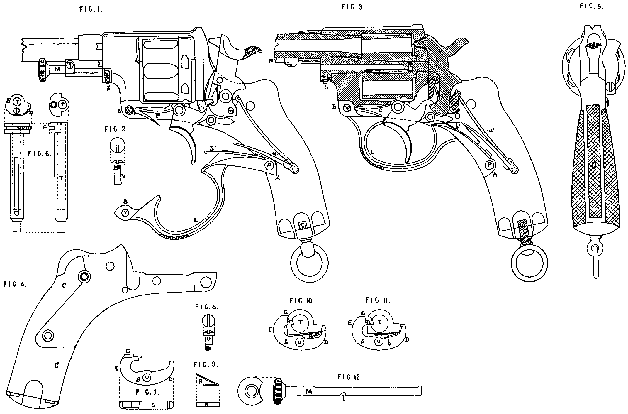
In the Drawings similar letters relate to like parts in all the Figures.
Figure 1 shews a revolver from which the side plate is removed, shewing the internal mechanism.
The bow of the trigger guard L is open, leaving free the main striking spring a¹, the seer spring b¹, and the trigger spring c¹.
Figure 3 shews a revolver, also without the side plate, part of the arm being seen in section. The bow of the trigger guard is closed; it cocks or places in tension the three springs above-mentioned.
As shewn in Figures 1 and 2 the bow of the trigger guard is fixed to the body by its two extremities, that is to say, at A upon a pivot P, and at B by a screw V.
When the bow of the trigger guard is open, as in Figure 1, the springs are uncocked or relaxed, which allows of the removal by the fingers of all the small pieces of mechanism The bow of the trigger guard itself is easily taken out, as on removing the screw V it is left free and may be withdrawn from the pivot P. The two points of attachment of the bow of the trigger guard being at a great distance from one another, the latter forms a powerful lever which serves to cock or place in tension the springs for the putting together of the mechanism.
In my revolver the inner faces of the handle of the body and of the side plate are both without flanges, and are flat, which simplifies the manufacture of the arm and facilitates cleaning the same. From this mode of construction there results an empty space in the handle of the arm between the body and the side plate. This Space is filled with a separate piece of wood, metal, or any other material fixed to one of the plates by a screw or other means. Figure 4 shews at C this piece fixed to the inner face of the side plate.
Figure 5 shews at C this same piece as seen from behind the handle of the revolver when the side plate is fixed to the body.
In my revolver the axial stem of the cylinder or cartridge chamber, Figure 6, has a hole T bored in it lengthwise to receive the extracting rod. The head of this stem is slotted in its thickness, see F, Figure 6. In this slot is placed the locking piece S, Figure 7, secured to the head of the stem by a screw pivot U, Figure 8, and pressed by a spring R, Figure 9, see also Figures 1 and 3.
Figure 10 shews the locking piece S pivoting upon its axis; the part D of the said locking piece projects outside the head of the stem by reason of the pressure of the spring R. The part E of the locking piece approaches the body of the stem. The projection G of the locking piece enters a notch formed in the body of the revolver, and thus prevents the axial stem of the cartridge chamber from coming out of its place, at the same time the projection H of the locking piece passes into the hole T of the axial stem through a lateral opening, and enters the notch I of the extracting rod M, Figure 12; the extracting rod is thus held firmly in the axial stem.
In Figure 1 the extracting rod M is seen in place under the barrel of the revolver, and enclosed in the axial stem of the cylinder or cartridge chamber; Figure 3 shews the extracting rod M withdrawn out of the stem, and turned to the side of the barrel for the extraction of the cartridge cases.
When it is required to draw out the extracting rod and the axial stem of the cylinder or cartridge chamber the finger is placed on the part D of the locking piece (see Figure 11). This part D enters the head of the stem; the part E, on the contrary, moves away; the projections G and H respectively leave the notch in the body and the notch I in the extracting rod (Figure 11), which allows the extracting rod to be drawn out of the stem, and the stem out of the cylinder or cartridge chamber and body.
Having now described the nature of my said Invention, and the manner in which the same is to or may be carried into effect, I would have it understood that what I claim as my Invention is,—
First. The arrangement and adaptation of the bow of the trigger guard so as to act as a spring vice, and forming a powerful lever for “cocking” or placing in tension instantaneously the principal springs of the mechanism.
Second. The construction of the body and side plate in such manner that the empty space between those two parts of the arm may be filled by a separate piece of wood or other material.
Third. The arrangement of the axial stem of the cylinder or cartridge chamber and of the extracting rod composed as follows:— A piece secured in-the head of the axial stem of the cylinder or cartridge chamber, such piece being pressed by a spring which forces a projection of the said piece to enter a notch in the body of the revolver, and another projection to enter a notch in the extracting rod.
In witness whereof, I, the said Emile Nagant, have hereunto set my hand and seal, this Seventeenth day of April, in the year of our Lord One thousand eight hundred and eighty.
EMILE NAGANT. (L.S)