
US 18836
UNITED STATES PATENT OFFICE.
ETHAN ALLEN, OF WORCESTER, MASSACHUSETTS.
IMPROVEMENT IN REVOVING FIRE-ARMS.
Specification forming part of Letters Patent No. 18,836, dated December 15, 1857.
To all whom it may concern:
Be it known that I, ETHAN ALLEN, of Worcester, in the county of Worcester, in the State of Massachusetts, have invented a new and useful Improvement in Repeating Fire-Arms; and I do declare hereby that the following is a full and exact description thereof, reference being had to the accompanying drawings, and to letters of reference marked thereon, in which drawings—
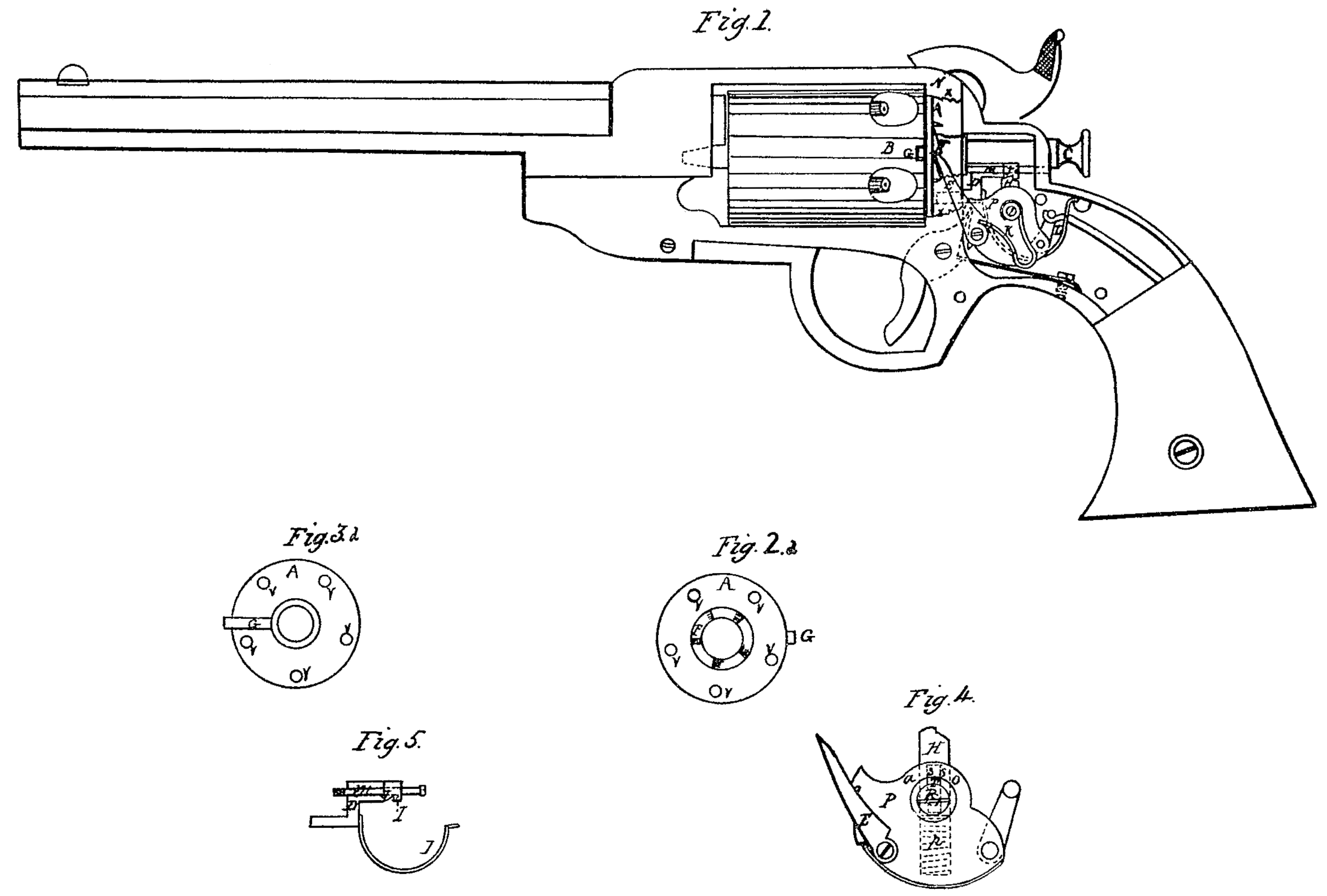
Figure1 is a representation of the pistol with its side plate removed to show the lock, also having a part of the breech-plate left out to show the arrangement for moving the cylinder. Fig. 2 is a back view of the circular plate with the ratchet-teeth upon it. Fig. 3 is a front view of the same plate, showing the projection on its face. Fig. 4 is an enlarged representation of the tumbler, showing the catch-pin with its spring; and Fig. 5 is the sliding lock-pin and its spring.
The same letters denote the same parts in each.
To construct my improvement, make a plate, A, at the rear end of the cylinder B, between it and the breech-plate N, and on the front side of this plate A form a projection, G, (see Fig. 3,) which shall fit into a radial slot in the rear end of the cylinder. This plate A may be held in its place by a hollow screw, as in this case, or otherwise, as may be deemed best. On the back of this plate A make a ratchet with radial teeth, F, (see Fig. 2.) for the catch E to work in to move the plate around its center. Also, between the ratchet and the periphery of the plate make a row of holes, v v v, or recesses, to receive the end of the lock-pin D, which holds the plate and cylinder in proper position with regard to the barrel in front while the pistol is being discharged. One object of this plate is to keep the moving and locking apparatus in a manner free from the cylinder, so that it may be more easily removed. The manner of accomplishing this removal will be herein after described.
Part of (Fig. 1) the breech-plate at x x is removed to throw the ratchet in place and the catch E that moves it. This catch works through a slot in the breech-plate, and is fastened to the lower part of the tumbler P by a stud-screw, and is pressed into the teeth of the ratchet by the spring K, attached to the shaft of the tumbler.
The lock-pin D is made as seen in Fig. 5, having a hole in its upper part, through which is put the screw m, on which it slides, and which also serves to guide its back end, while its front end slides in a hole in the breech-plate. The round part of this pin is just long enough to reach through the breech-plate and the plate A when thrown forward by its spring. The back end of this lock-pin has in its under side a notch or indent, i, to receive the catch on the top of the pin H in the top of the tumbler. It has also in front of this notch a cam face or projection, J, for the purpose of pressing down the pin H when it is drawn far enough back, and in this way throwing the catch out of the notch i, leaving the pin D free to be thrown forward against the plate A by its spring L.
The tumbler is constructed as seen in Fig. 4, which is on a scale twice the usual size. The most important piece in this part of my invention is the pin H, inserted in the top of the tumbler and extending down past its axis, as shown by the dotted lines o o. This pin has a slot through its middle lengthwise of the pin, as shown by the dotted lines S S. Through this slot is inserted the screw-pin R in the center of the axis of the tumbler, which keeps the pin H in its place and prevents it from turning, so that the catch on the top of the pin shall always face in the proper direction to catch in the notch i. This pin E is pressed out by a spring, P, which allows of its being pressed down by the projection J to free the catch from the lock-pin D.
To operate my improvement, draw back the hammer to the first notch, or what is called “half-cock.” In doing this the catch-pin H in the tumbler takes into the notch in the lock-pin D and moves it far enough back to clear the plate A. The catch E now comes in contact with one of the ratchet-teeth E and begins to move the plate A. By pulling the hammer a little farther back the projection J of the lock-pin will press the catch-pin H down so far as to release the lock-pin, which will be immediately thrown forward against the plate A by its spring; but by this time the catch E has moved the plate A so far that the lock-pin cannot enter the last hole, but presses against the plate in readiness to enter the next hole when the plate has been moved far enough, which is done by bringing the hammer back to full-cock. This division of time between the motions of the different parts insures, first, that the catch will not begin to move the plate before the pin which holds it is withdrawn; second, that the plate will not fail to move, as the motion of the catch is a positive one; third, that the plate cannot be carried too far, because the lock-pin is pressing against it ready to enter the hole some time before it is brought to position, so that, however quickly the action of drawing back the hammer may be performed, the action of each part will be sure to be correct. As I have before stated, one object of this plate A is to facilitate the removal of the cylinder B. To accomplish this removal, draw back the lock-pin D by pulling the hammer back to half-cock, when the plate and cylinder will be at liberty to turn in one direction. Then turn the cylinder until the projection G is in a horizontal position, being either on the right hand or left-hand side of the pistol. It makes no difference which, Now remove the center-pin C, and the cylinder can be slid out on the side opposite to which the projection shall be. This plate A, as described, is the most important part of the improvement, for by it. We are enabled to act upon the cylinder so much farther from the center in moving and locking it that it is set and held in position far more accurately and securely, at the same time keeping the parts that perform the turning and holding in a manner separate from the cylinder, so as not to interfere with its removal.
What I claim as my invention, and desire to secure by Letters Patent, is—
The plate A, made and operating substantially as herein described.
In witness whereof I have hereunto set my hand in the presence of two witnesses.
ETHAN AILLEN.
Witnesses:
W. S. Davis,
Benjamin Arnold.