
US 19739
UNITED STATES PATENT OFFICE.
F. D. NEWBURY, OF ALBANY, NEW YORK, ASSIGNOR TO R. V. DE WITT, JR.
IMPROVEMENT IN REVOVING FIRE-ARMS.
Specification forming part of Letters Patent No. 19,739, dated March 23, 1858.
To all whom it may concern:
Be it known that I, Frederick D. Newbury, of the city of Albany, State of New York, have invented certain Improvements in the Class of Fire-Arms known as “Revolvers;” and I declare the following specification, with the drawings hereto attached as part thereof, to be a full and complete description of the same.
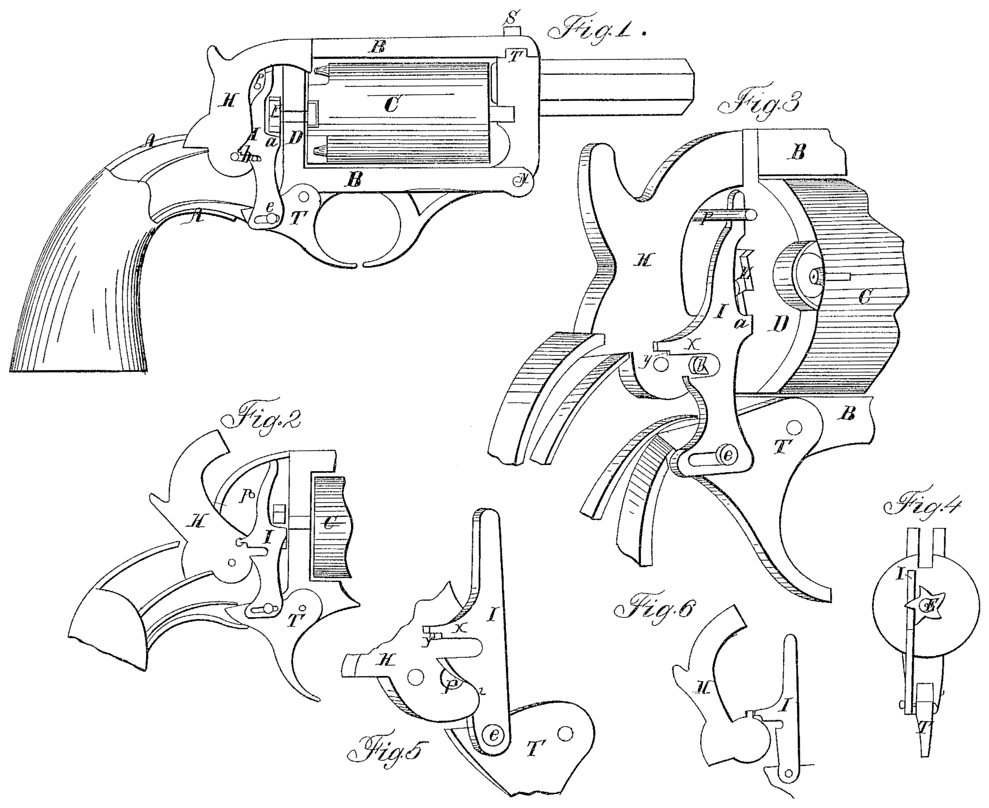
Figure 1 is a profile view of a revolver-pistol With the outer casing of the stock partially removed to show the mechanism of the piece. Fig. 2 is a representation of the same mechanism, the working parts being in a different position from Fig. 1. Fig. 3 is a perspective view of the arrangement shown in Fig. 1 on an enlarged scale. Fig. 4 is a reverse view— i.e., from the front— of ratchet wheel and lever. Figs. 5 and 6 are diagrams exhibiting an arrangement of lever and pin as substitutes for that shown in the other figures.
Similar letters in all the figures denote the same parts of the apparatus.
A is the skeleton-stock framing of a pistol expanded into a frame, B, intended to hold the usual revolving cylinder, C. This cylinder turns upon steel axles (seen in the drawings) projecting from each end of the same, the one passing into or through the front bar of the frame, the other through the rear bar, being the “face-plate” D, so called, behind and against which it carries the ratchet-wheel E. By this wheel the cylinder C is turned round by the movement of the ratchet-lever I, the peculiar shape of which will be understood from the drawings and the explanation hereinafter of its functions. I employ a cylinder with solid center revolving on external axes in preference to one with a hollow center, because it enables me to reduce its size, consequently the thickness and weight of the weapon, by bringing the chambers nearer together and yet leave sufficient strength of metal at the axis of the cylinder; also, because it is not liable to foul from the fumes of the powder, and so become difficult to detach from the piece when needed, which frequently occurs when the barrel turns upon a mandrel.
The lever I is pivoted to the rear limb of the trigger T by a pin, e, movable in a slot in the lever, or vice versa, so that it can move freely up and down in the direction of its length, and at the same time its lower end slides backward and forward easily. The lever operates the wheel E by a forward projection, a, which, lying under a tooth of the wheel, forces it round as the lever moves upward, the upper part of the lever being guided and kept in place by a pin, p, or by the casings of the frame shaped for that purpose. To hold the cylinder firmly in position at the act of firing the projection a of the lever I is fitted to conform to the spaces between the teeth of wheel E, (see Figs, 3 and 4) so that when the lever is held at the top by the pin or stock-casing and at the bottom by the trigger the wheel is effectually blocked.
On the front limb of the hammer H, about opposite to its axis, there is a pin, b, projecting from it, fitted to slide into a shallow notch or recess cut into the back of lever I, so that when the hammer is down (see Figs. 1 and 3) the pin shall lie in the bottom of the recess. When a pull on the trigger raises the lever the pressure on this pin b turns the hammer on its axis, the pin moving backward in the notch until it is disengaged therefrom, when the hammer will be free to fall forward or down to its first position. Then when the trigger falls back by the play of pine in the slot on the lever the lever is enabled to slip round the pin b, so as to enable the pin to re-enter the notch to its first position. It will be seen that the upper part of the lever is so shaped that while its projection a, resting against the face-plate D, acts as a fulcrum the pin p shall press, the notch in the lever over pin b.
The slot in the lever may be dispensed with, and the lever pivoted to the trigger with a pin, e, by giving to the lower jaw of the notch, as shown in Fig. 5, a slope on its inner side from its full thickness at 1 to a lower point, 2, so that when the hammer has fallen and the pin p lies below and in the range of the jaw the lever in coming down may be pressed sidewise, which its elasticity will permit, until the notch reaches the pin, over which it will spring into its first-described position.
As an equivalent for the pin p a projection may be used on the front edge of the hammer instead of from its side, as shown in Fig. 6.
The apparatus, arranged as described, permits the piece to be cocked and fired repeatedly by successive pulls of the trigger; but it being desirable for more accurate shooting to be enabled to cock or set the hammer and discharge it by a less strain on the trigger than this will allow, I accomplish this object by the following means:
The lever I has a back limb or prolongation, x, of that part which lies over the notch in which pin b moves, at the lower back corner edge of which there is a shallow offset, y. The pin b has a rectangular nick cut into its front edge or surface, (see Fig. 3,) and the length of x is so adapted to the course of the pin that when the hammer is drawn back by the hand the front angle of the offset shall drop into the nick of the pin. The shallowness of the offset gives x so slight a hold on the pin that a slight touch on the trigger will disengage them and drop the hammer, making a hair-trigger movement. By drawing the hammer farther back the back end of x enters the full depth of the nick, requiring a stronger pull to disengage it. (See Fig. 2.) This arrangement secures safety from a careless use of the hair-trigger arrangement, inasmuch as ordinary pressure on the hammer in cocking the piece will carry it to its farthest position, for it will require a delicate and designed movement to set, it in its first position.
In order to disengage the cylinder C from the frame B, the front bar to which the barrel is attached is movable, and is hung on a hinge, N, to the lower bar of the frame, the upper end resting in a notch or groove, r, cut across the upper bar, the spring of the bar being sufficient to permit its passage into the notch. It is secured by a screw, S, which passes through the upper bar into it, its head being fitted to serve as a sight.
What I claim, and desire to secure by Letters Patent, is—
1. The lever I, formed and fitted as described, or its substitute, as described, for the purpose of cocking the hammer, holding the same when it has been cocked by hand, rotating the cylinder, and holding the cylinder firmly in the act of firing.
2. The hammer, with its pin b, in combination with lever I, for cocking by hand.
3. The combination of hammer, lever, ratchet-wheel, and trigger, arranged substantially and for the purposes set forth in this specification.
F. D. NEWBURY.
Witnesses:
E. J. Miller,
Richd. Varick Ide Witt.