
US 27868
UNITED STATES PATENT OFFICE.
FREDERICK D. NEWBURY, OF ALBANY, NEW YORK, ASSIGNOR TO RICHARD W. DE WITT, JR, OF, SAME PLACE.
IMPROVEMENT IN REVOLVING FIRE-ARMS.
Specification forming part of Letters Patent No. 27,868s, dated April 10, 1860.
To all whom it may concern:
Be it known that I, Frederick D. Newbury, of the city of Albany, State of New York, have invented certain Improvements in the Construction of Fire-Arms; and I declare the following specification, with the drawings hereto attached as part of the same, to be a full and perfect description of my invention.
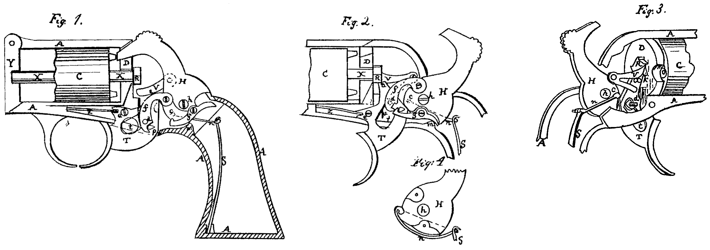
Figure 1 represents in profile the skeleton-frame of the handle of a pistol, the covering plate and wooden gripes being removed to show the mechanism of the lock, the position of its parts being as ready for firing by the trigger. Fig. 2 is the representation of the parts with the hammer cocked and ready for firing. Fig. 3 is a perspective view, showing the mechanism in reverse of Fig. 2. Fig. 4 is a diagram to show a peculiar method of attaching the mainspring to the hammer.
Similar letters in all the figures denote the same parts of the apparatus.
My invention applies directly to revolvers, but may be used to some extent in the locks of common fire-arms.
A is the skeleton stock-frame, holding the usual revolving cylinder, C. This cylinder turns upon a shaft or axis, X, extending through its length, carefully fitted, so that the cylinder can be easily slipped from it, but by a feather and slot, pin and notch, or other convenient device, so fitted that the revolution of X shall carry the cylinder with it. The front end of the shaft rests within a cross-bar, Y, forming the end of the frame A, and its rear end through the face plate or bar D, behind and against which it carries the ratchet-wheel R, firmly attached to it, (the shaft.) By this wheel the cylinder is turned through the action of >-shaped lever V and the trigger T. The edge of wheel R is cut into ratchet-teeth corresponding with the number of chambers in the cylinder-five for a five— shooter, six for a six-shooter.
The trigger T, shaped as shown in the drawings, is pivoted to the frame at e, and has projecting from its upper back corner a limb, a, fitted to conform to the space between the teeth of R, so that when the trigger is held back in the act of firing— that is, is moved a little back of its position, as shown in Figs. 2 and 3— it shall block the wheel, holding the bores of the chamber and barrel in line with each other.
The hammer H is pivoted to the frame at h. Toward its front edge is pivoted a bar or link, f, which by its other notched end, fitted to a spin, p, upon the trigger, maintains the connection of hammer and trigger, so that the drawing of the latter shall throw the former backward. Toward the bottom of the hammer the balance catch-lever g is pivoted, having at its front end a hook or catch fitted to hold onto p, its back end being so shaped that when by the-movement of the hammer it is thrown for ward it can be canted upward by a projection in the frame or pin placed at m for the purpose. This movement is to direct the hook end toward the pin p, as hereinafter explained, and for the same purpose the back end of the lever is stopped by appropriate means upon or against the hammer.
To guide the movements of bar f, it has a pin, d, projecting back through a slot, t, made through the trigger, and against this pin a spring, u, Fig. 2, attached to the frame, is arranged to press the notch of the bar over pin p when hammer and trigger are both down, as in Fig. 1.
The >-shaped lever V is attached to the frame behind the hammer, and is operated by a pin, k, projecting from the end of limb a of the trigger, as shown in Fig. 3. It has a small spring lying behind it, which cannot be shown in the drawings, to keep it pressed habitually up from the frame toward the trigger.
The trigger T is kept in its proper position, when at rest, by sear-spring Z.
The operation of the mechanism is as follows: The cylinder being loaded and capped and the parts of the lock in the position shown in Fig.1, a pull upon the trigger, pressing upon pin p, throws the hammer backward by the barf, and continues to move it back until the progress of the bottom of the hammer carries lever g so far forward that it passes under pin p, when it trips f from the pin and the hammer falls. During this movement the upper limb of lever V, lifted by the pink on the trigger, passes under and presses up one of the teeth of the wheel R, turning the cylinder until one of the chambers is in range, or nearly so, with the bore of the barrel, bringing a cone and cap in the range of the hammer, the last movement of the trigger bringing its end a firmly against and blocking the wheel as the hammer falls. As soon as the trigger is relieved it is thrown back by the sear-spring, and in its progress downward pink, pressing upon the lower limb of V, carries the upper limb downward along and below the ratchet-tooth, against which it laid, and is then by the pressure of the spring beneath it thrown under the tooth, ready to lift it on the next pull of the trigger. At the same time barf, forced by the action of spring u upon pin d, takes its place upon pin p, and all is ready for another fire.
This piece can also be cocked by hand, for it will be seen that by raising the hammer the trigger will follow until lever g trips f, when, as the hammer is held from falling at the instant of the trip, time is given for the catch at the end of g to slip over pin p and hold the trigger from falling back until it is pressed by the finger back a small distance, which lifts the pin until it is disengaged from the hook, when the hammer falls and the trigger falls back to it first position.
What I claim, and desire to secure by Letters Patent, is—
1. The apparatus for enabling the hammer and trigger to be operated in concert with each other, whether the hammer be set by hand or by the trigger.
2. The bar f, attached to the hammer and working along the side of the trigger in order to catch into the pin p, in combination with the balance catch-lever g, operating as described.
3. Pin d in barf, operating through the slot t, and in combination with it and spring u, or the mechanical equivalents for said apparatus, the whole operating together in manner and for the purposes set forth.
4. The combined action of the trigger and pink with lever V in operating the cylinder, so that when the lever has turned the cylinder to bring a chamber in it and the barrel to coincide the toe or front point, a, of the trigger shall, jointly with the pin k and the lever V, hold the cylinder during the discharge of the piece, in the manner herein shown and described.
F. D. NEWBURY.
Witnesses:
Richd. Varick De Witt,
A. V. De Witt.