
US 30494
UNITED STATES PATENT OFFICE.
FREDERICK D. NEWBURY, OF ALBANY, NEW YORK.
IMPROVEMENT IN REVOLVING FIRE-ARMS.
Specification forming part of Letters Patent No. 30,494, dated October 23, 1860.
To all whom it may concern:
Be it known that I, Frederick D. Newbury, of the city of Albany, State of New York, have invented certain Improvements in the Construction of Fire-Arms of the kind denominated “Revolvers;” and I declare the following specification, with the drawings hereto attached as part of the same, to be a full and perfect description of my invention.
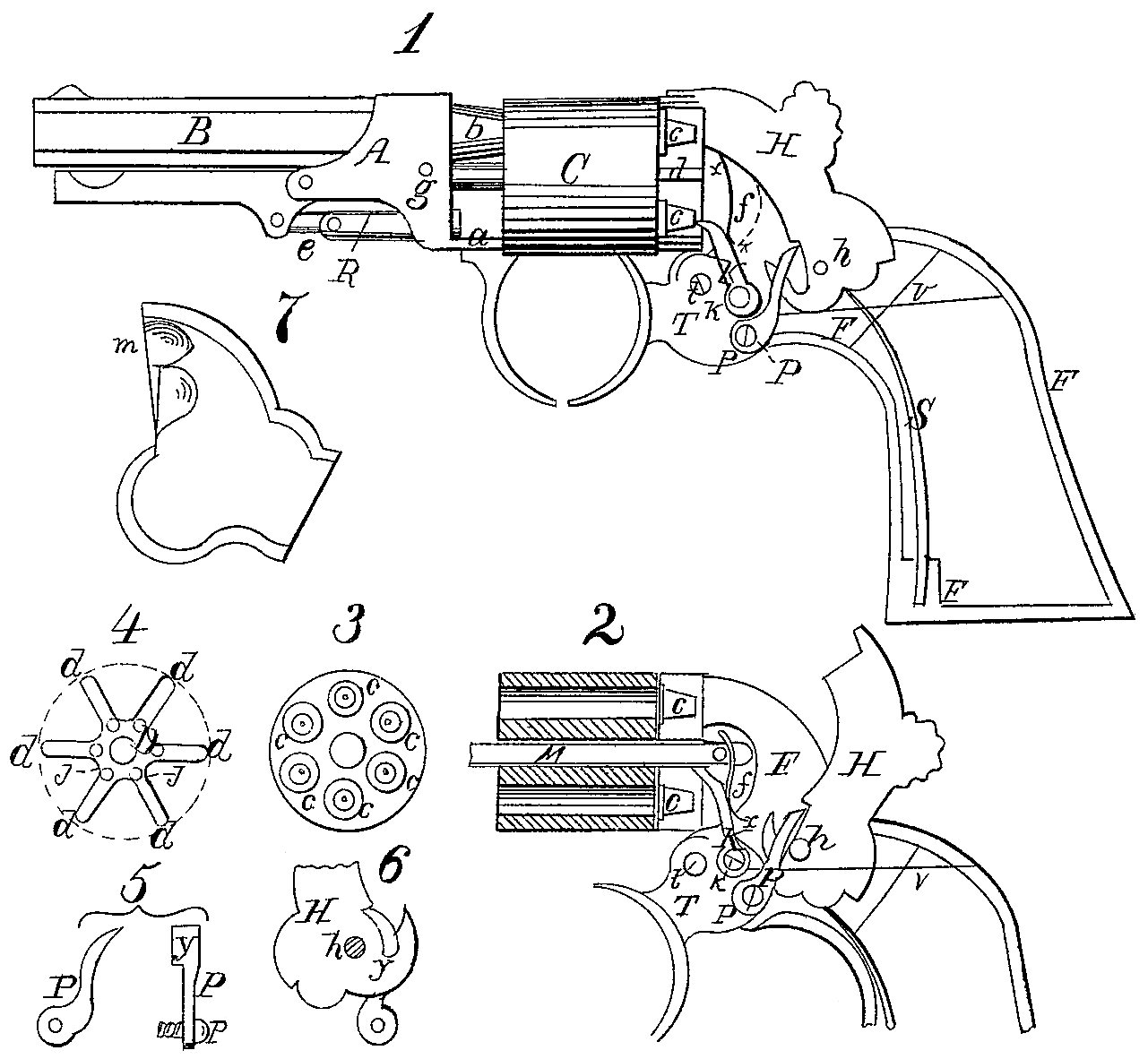
Figure 1 represents a pistol in profile, the left-hand cap or cover of the lock removed to permit an inspection of the lock-work, and the wooden gripes of the handles also removed, showing its skeleton-frame. The parts of the lock are shown in position previous to the act of cocking. Fig. 2 is a profile diagram, showing the position of the parts of the lock when the hammer is cocked, the frame and cylinder being in vertical central section. Fig. 3 is a rear view of the load-cylinder with the priming-cones in place. Fig. 4 is a plan of the cones’ division-plate, which lies between the cylinder and the recoil-shield. Fig. 5 shows the pawl which operates between the trigger and hammer in two positions. Fig. 6 shows the operation of the pawl upon the hammer as seen from the right-hand side thereof. Fig. 7 represents a left-hand cheek-piece of the frame with the capping-notch.
Similar letters in the different figures denote the same parts of the apparatus.
The metal frame F is in the usual form. It has its side plate at funder the hammer thickened up, so as to present a good face in front and to form a firm base to receive the rear end of the mandrel M, (see Fig. 2.) forming what is called the “recoil-shield.”
The mandrel is to carry the load-cylinder C, which revolves upon it freely. The end of the mandrel beyond the cylinder supports the barrel-socket A, into which it enters, and is secured by the pin g. This socket serves to hold the barrel B b and the ramrod R with its lever E and link e. The lower part of A has a limb, a, projecting backward until it touches the front face of the cylinder C, which rubs against it as it revolves. The object of this limb is in conjunction with that part of the barrel b which projects backward against the cylinder to steady the barrel in the act of firing.
Between the cylinder C and the recoil-shield f is the cone division-plate D, which occupies the entire space betwixt them. It is shown in plan in Fig. 4, and consists of a center boss, D, with flat radii, d, projecting from it to its outer edge. The boss is pierced with an orifice for the passage of the mandrel M. The radii d d have space between them for the priming cones c c, Figs. 1 and 3. This plate D moves with the cylinder C, to which it is attached by pins projecting from the one entering into corresponding pin-holes in the other. The object of this plate is to form walls to prevent fire communicating from one priming-cap to another, also to retain the broken (exploded) caps in place until the revolution of the cylinder shall bring them to the bottom of its circuit, when they will fall off from the cones.
The machinery of the lock consists of the following parts: The hammer E, lying, when down, in a slot within the center of the top of the frame, turning upon a pivot, h, just in front of Which it has a peculiarly-shaped notch and hook or claw, distinctly shown in Figs. 1, 2, and 6. The trigger T, pivoted at t, near its back lower edge, has a pawl, P, pivoted at p, Figs. 1, 2, 5, and 6, its upper point entering into the notch of the hammer, This point is made broad, so as to project with a shoulder, y, as seen from the front, over the notch and fitting into it. Just above this is another pawl, K, pivoted at k, its upper point bent forward and made tapering, in order to enter into, when pressed upward and slip out when drawn downward, holes j j, made in the cone division-plate D, as shown at Fig. 4. Pawl P is kept pressed against the hammer by a spring, v, pressing downward upon a pin in the side of the pawl. This spring is so arranged as to its direction that when the trigger is held back and the hammer is in the act of falling its pressure shall be in the direct line from the pin it rests upon to the pivot of the pawl P. Pawl K is kept up to the plate D by spring x.
S is the mainspring, which may be attached to any suitable part of the frame, its upper point passing under a notch, n, in the base of the hammer.
There is in all revolvers where the recoil-shield covers the entire end of the cylinder a notch cut into the shield or the cheek-plate of the frame, which extends over and forms part of it, called the “capping-notch,” for the purpose of giving admission to the caps to the cones in priming. It is placed on the right-hand side of the hammer, the cylinder revolving from left to right. This I require to be placed on the left-hand side and next to the hammer, when the cylinder turns from left to right, and vice versa, in order that no cap broken by the hammer shall pass over the notch and endanger blocking of the cylinder. Fig. 7 shows a left-hand cheek-plate of the frame in profile, m being the notch.
The operation of the piece is thus : After being loaded and capped in the usual manner, draw back the hammer by the thumb. Then the hook end at the notch, seizing upon the projecting shoulder of pawl P, draws the rear end of the trigger upward until the shoulder fits into the notch in the position shown in Figs. 2 and 6, blocking the hammer there. At the same time pawl K, having been lifted upward, turns the plate D with the cylinder, bringing one of its chambers in range with the barrel and its cone in range with the hammer, holding it firmly there as long as there is any pressure upon the trigger. A slight pull upon the trigger forces the hammer back and trips the pawl P out of the notch, allowing the hammer to fall upon the cone. So soon as the trigger is released the pressure of spring v throws it back to its first position, as in Fig. 1, when the pawls take their places, P under the notch in the hammer, and K in the succeeding hole in plate D.
The piece can also be cocked and fired from the trigger alone. A pull upon it brings the pressure of pawl P against the hammer-notch, throwing it back until it is forced out of the notch, and the hammer falls, the hammer operating the trigger and the cylinder, as just described.
The advantages which I propose to attain by the above construction are these, viz:
First. Dispensing entirely with the usual straps or bars connecting the lock-frame with the barrel-socket prevents the blocking of the cylinder by fragments of exploded caps, to which revolvers are exceedingly liable, in as much as there is no crevice between parts in which anything can lodge.
Second. The arrangement of spring V permits it to operate both as a pawl-spring and a sear-spring to press the trigger to its place when released from the pressure of the finger, saving a spring in construction. Also, the line of bearing of this spring is such that there is no pressure against the pawl when the hammer is descending, relieving the mainspring from the need of a counteracting pressure, necessary when the spring is arranged in the usual manner.
Third. In the arrangement of the ratchet pawl Kit will be seen that it not only operates as a pawl, but with its point fixed within the hole i it makes a perfect lock to the cylinder, holding it immovable so long as the finger presses the trigger back, thus saving an extra bolt, with its spring.
Fourth. Arranging the cone division-plate ID separate from the cylinder permits the making of it cheaply of malleable iron, while it allows it to be case-hardened or tempered against wear. Also, it makes the fitting, removal, and replacing of cones an easier and less costly matter than where the cap-cells are formed in the cylinder itself.
Fifth. The position of the capping-notch, as described, prevents any crevice where by possibility a cap-fragment could lodge. If placed, as usual, on the other side of the hammer, it would be possible for a small fragment of a cap to slip out and catch as the cone passed the notch.
What I claim, and desire to secure as my invention by Letters Patent, are the following devices, substantially as described in the within specification and for the purposes therein set forth, to wit:
1. The cocking-notch lying at the base of the hook or claw of the hammer, as described, in combination with the shoulder y of the pawl P.
2. The spring v, so arranged as by one operation to regulate the pawl P, and at the same time act as a sear-spring upon the trigger.
3. Ratchet pawl K, pivoted to the trigger, fitted and formed to act as a pawl and bolt, in combination with the holes j j in plate D.
F. D. NEWBURY.
Witnesses:
Richd. Varick De Witt,
A. W. De Witt.