
US 235240
Modernized LeMat
United State Patten Office.
FREEMAN W. HOOD, OF NORWICH, CONNECTICUT.
REVOLVING FIRE-ARM.
SPECIFICATION forming part of Letters Patent No. 235,240, dated December 7, 1880.
Application filed October 9, 1880. (No model.)
To all whom it may concern:
Be it known that I, Freeman W. Hood, of Norwich, of the county of New London and State of Connecticut, have invented a new and useful Improvement in Revolvers; and I do hereby declare the same to be described in the following specification and represented in the accompanying drawings, of which—
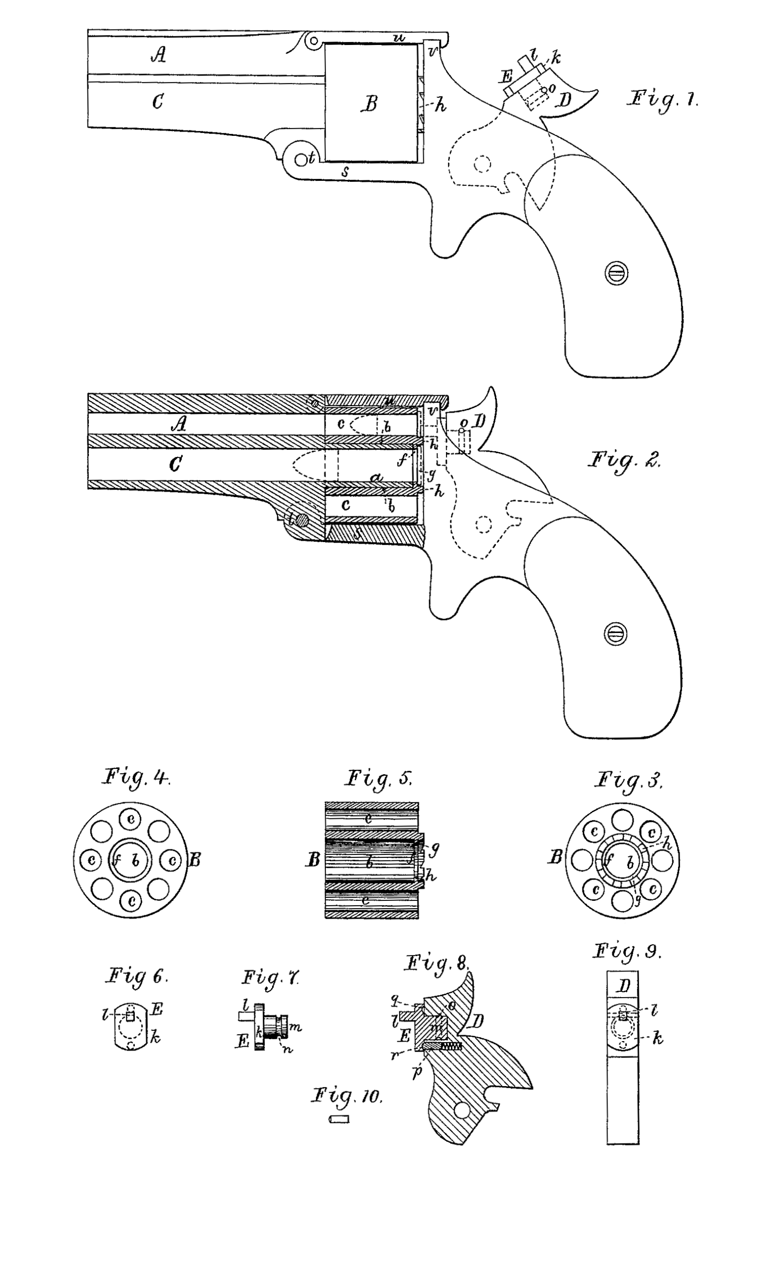
Figure 1 is a side view of a revolver containing my invention; Fig. 2, a longitudinal section of it in part, such showing the cylinder and barrels. Fig. 3 is a rear-end view, Fig. 4 a front-end view, and Fig. 5 a longitudinal section, of its rotary charge-cylinder. Fig. 6 is a front view, and Fig. 7 a side view, of the eccentric striker of the hammer. Fig. 8 is a vertical section, and Fig. 9 a front view, of the hammer and its eccentric striker. Fig. 10 is a top view of the spring-bolt p, hereinafter described.
The mechanism for operating the hammer is not shown, as it is to be of any proper kind and constitutes no part of my invention.
A fire-arm containing my said invention has, besides the rotary charge-cylinder and its barrel, an auxiliary barrel arranged below or beside of the first-named or main barrel, and having its axis in line with that of the said cylinder, and such fire-arm is or should be provided with a lock having means for firing or striking a cartridge adapted to either of the charge-chambers of the cylinder or to the auxiliary barrel.
In the drawings, A denotes the main barrel; B, the rotary charge-cylinder, and C the auxiliary barrel, the latter being arranged under the main barrel and extended axially into the cylinder, the extension being represented at a, it being tubular, and constituting a journal to support the cylinder and for it to revolve upon. The cylinder at its axis is bored to receive and fit to the tubular extension or journal a, the bore b being concentric with the series of charge-chambers c of the said cylinder. At the rear part of the bore of the cylinder there is an annular shoulder, f, for the rear end of the extension at to abut against, the inner diameter of the said shoulder corresponding in size to the diameter of the rear end of the bore of the extension or auxiliary barrel. Furthermore, besides the annular shoulder, there is at the rear end of the axial bore of the cylinder an annular groove or recess, g, for reception of a cartridge-shell head when the body of the said shell may be within the bore of the extension of the auxiliary barrel. Concentric with the said recess, and around it, as shown, is the ratchet or series h of teeth for aiding in effecting revolution of the cylinder.
The hammer of the lock is represented at D as provided with means or a device for striking the rear part or end of a cartridge of the auxiliary barrel, or that of one in either of the charge-chambers of the cylinder when such chamber may be uppermost, the said means or device, as represented, consisting of an eccentric striker, constructed and adapted to the hammer, so that on being turned up such striker will, on the hammer being thrown down by its spring, be made to strike a cartridge of the cylinder without contact with one in the auxiliary barrel, and on being turned down will, on the hammer being thrown down, strike the cartridge in the auxiliary barrel without contact with a cartridge in the then upper charge-chamber of the cylinder. The said device is shown at E, and consists of a disk, k, pivoted on the hammer, and provided with a stud or projection, l, extending from its front face eccentrically to the center of the disk, or the axis of the journal m of such disk.
There is a groove, n, in and around the said journal, such groove being to receive a pin, o, inserted in the hammer. There is also just below the journal a spring latch or bolt, p, which latches into either of two cavities, q r, in the disk, in order to hold the stud l in either of its positions. The front end of the bolt is crowned or arched, as shown in top view in Fig. 10, in order for the bolt to be forced back and disengaged from either cavity when an attempt is made to revolve the eccentric striker by manual power.
The combined barrels are pivoted or hinged to a projection, s, of the stock, the hinge being shown at t, and the said combined barrels are provided with a notched latch, u, hinged to them and extended over the cylinder, and constructed to work upon or engage with the breech of the upper part, v, of the stock. On throwing up the said latch out of engagement with the part the barrels, with the cylinder, may be turned down, so as to uncover the rear end of the cylinder for loading it, unloading it, or for removing from it any one or more of the charges or shells thereof, as occasion may require.
The bore of the auxiliary barrel can be made of larger caliber or diameter than that of the main barrel, in order to receive and discharge cartridges of larger size than those of the main barrel, thereby rendering the weapon more effective for some purposes or uses than an ordinary revolver would be.
I am aware that prior to my invention it has been customary to construct a revolver with two barrels, in which case the rotary charge-cylinder to operate therewith was not made or provided with a terminal shoulder and a cartridge-head-receiving recess arranged at the rear part of its central bore, as is the case with the revolver hereinbefore described, such serving to sustain the cartridge of the auxiliary barrel and cause it to be extracted therefrom by the cylinder while being withdrawn from the cylindrical and tubular extension of the said auxiliary barrel.
What I claim as my invention is as follows:
1. In a revolver, the combination of the main and auxiliary barrels, arranged as described, with a rotary charge-cylinder provided with the central bore and its terminal annular shoulder, and a series of charge-chambers, and arranged to turn on an extension of the auxiliary barrel into it, as set forth, the connected barrels being hinged to the stock, and the tubular extension of the supplemental barrel and the annular flange-cylinder together serving to form a chamber for the reception of a cartridge, when arranged in such tubular extension.
2. The combination of the main-and-auxiliary barrels, arranged as described, with a rotary charge-cylinder provided with a central bore, a terminal shoulder, and a cartridge-head – receiving recess, all as set forth, and arranged with and to revolve upon an extension of the auxiliary barrel, the connected barrels being hinged to the stock, and the tubular extension of the supplemental barrel and the annular flange-cylinder together serving to form a chamber for the reception of a cartridge, when arranged in such tubular extension, all being substantially as specified and represented.
FREEMAN W. HOOD.
Witnesses:
S. A. Gilbert,
W. S. Congdon.