
US 466952
UNITED STATES PATENT OFFICE.
GEORGE F. BROOKS, OF WORCESTER, MASSACHUSETTS, ASSIGNOR TO THE
HARRINGTON & RICHARDSON ARMS COMPANY, OF SAME PLACE.
SEAR AND REBOUND-CATCH FOR REVOLVERS.
SPECIFICATION forming part of Letters Patent No. 466,952, dated January 12, 1892.
Application filed September 9, 1891. Serial No. 405,160. (No model.)
To all whom it may concern:
Be it known that I, GEORGE F. BROOKS, a citizen of the United States, residing at Worcester, in the county of Worcester and State of Massachusetts, have invented a new and useful Improvement in Revolvers, of which the following, together with the accompanying drawings, is a specification sufficiently full, clear, and exact to enable persons skilled in the art to which this invention appertains to make and use the same.
This invention relates to the construction of the rebounder and sear, and to the manner of combining said parts with the trigger and hammer, the object being to provide and adapt a rebounder mechanism in connection with that class of lock mechanism in which a hinged lifter attached to the trigger is employed instead of a fly pivoted to the hammer, and in which mechanism a sear is a necessary part.
The essential feature of my invention consists in providing the rebounder with a slot or recess for the sear, arranging the sear through the rebounder, and pivoting both upon the same axis-stud in the manner illustrated in the accompanying drawings, wherein—
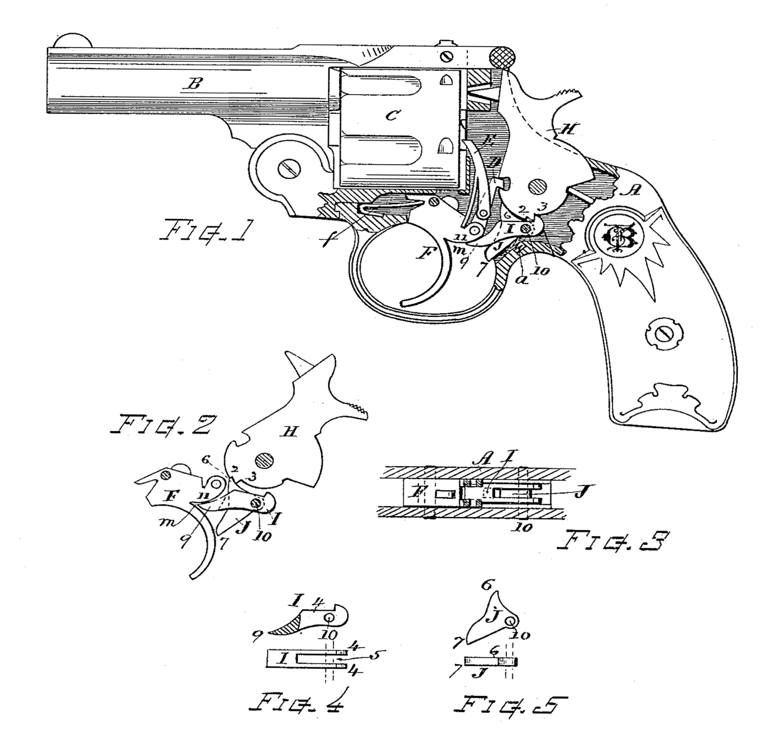
Figure 1 is a side view of a revolver constructed in accordance with my invention, a portion of the frame being shown broken away to reveal the parts of the lock mechanism. Fig. 2 is an outline diagram of the hammer, trigger, rebounder, and sear at position of full-cock and at the instant previous to the discharge. Fig. 3 is a horizontal section showing the lateral relation of the trigger, rebounder, and sear. Fig. 4 shows in detail the form of the rebounder, and Fig. 5 the form of the sear separate from the other parts.
In the construction of the revolver here shown the frame A, barrel B, cylinder C, lifter D, and hand or pawl E are made and disposed in well-known form, or substantially as described in Letters Patent No. 408,457, as are also the forward part of the trigger F, its spring f, and pivoting-axis, and the top of the hammer H, its lifter-engaging recess, and the mainspring connection. The lower portion or tumbler of the hammer is fitted with a sear-notch 2 and a shoulder 3 of the form shown. The rebounder I is made, as shown in Fig. 4, of bifurcated form or having two side plates 4, with a slot or opening 5 between them, and the sear J is made, as shown in Fig. 5, of such form that it will fit within said slot passing through the rebounder, with its point 6 in position for engaging the notch 2 of the hammer-tumbler and its end 7 at position to be acted upon by the back surface of the trigger F when the latter is pressed for discharging in the usual manner. The head of the rebounder I is fitted to catch onto the shoulder 3 on the hammer-tumbler, and the head of the trigger I is fitted with a rounded surface 11 for depressing the front point 9 of the rebounder for giving the rebound impulse when the trigger is swung forward in manner substantially similar to the action of rebounders heretofore separately employed. Both the rebounder and sear are pivoted upon the same axis-stud 10 and swing thereon independently of each other. A spring a is provided for throwing forward the sear. The rear of the trigger is fitted with a cavity or inwardly-tapered recess m between rounded surfaces 11, that engages with and fits the point of the rebounder when at backward position, thereby throwing the rebounder-head away from the hammer-tumbler just before the sear is thrown from the notch 2, so that the shoulder 3 will not strike the rebounder as the hammer falls.
By constructing the sear and rebounder in the manner shown a very desirable, economical, and efficient lock mechanism is produced.
I claim as my invention herein to be secured by Letters Patent—
1. In lock mechanism for revolving firearms, the combination of a sear and a rebounder, both pivoted upon a common axis-pin, one of said parts extending through a slot or recess formed within the other of said parts and disposed for engaging with the hammer-tumbler and trigger, respectively, at their opposite ends, substantially as set forth.
2. The bifurcated or slotted rebounder and the sear arranged through the same, both said sear and rebounder pivoted upon the same axis-pin, in combination with the hammer, its tumbler provided with the sear-notch and rebounder-shoulder, as shown, and the trigger having the inward recess and rounded surfaces for respectively engaging said sear and rebounder, substantially as and for the purposes set forth.
Witness my hand this 8th day of September, A. D. 1891.
GEORGE F. BROOKS.
Witnesses:
CHAS. H. BURLEIGH,
ELLA P. BLENUS.