
US 47712
UNITED STATES PATENT OFFICE.
GEO. H. GARDNER, OF NEW YORK, N.Y.
IMPROVEMENT IN REVOLVING FIRE-ARMS.
Specification forming part of Letters Patent No. 47,712, dated May 16, 1865.
To all whom it may concern:
Be it known that I, George H. Gardner, of the city, county, and State of New York, have invented a new and useful Improvement in Revolving Fire-Arms; and I do hereby declare that the following is a full, clear, and exact description thereof, which will enable others skilled in the art to make and use the same, reference being had to the accompanying drawings, forming part of this specification, in which—
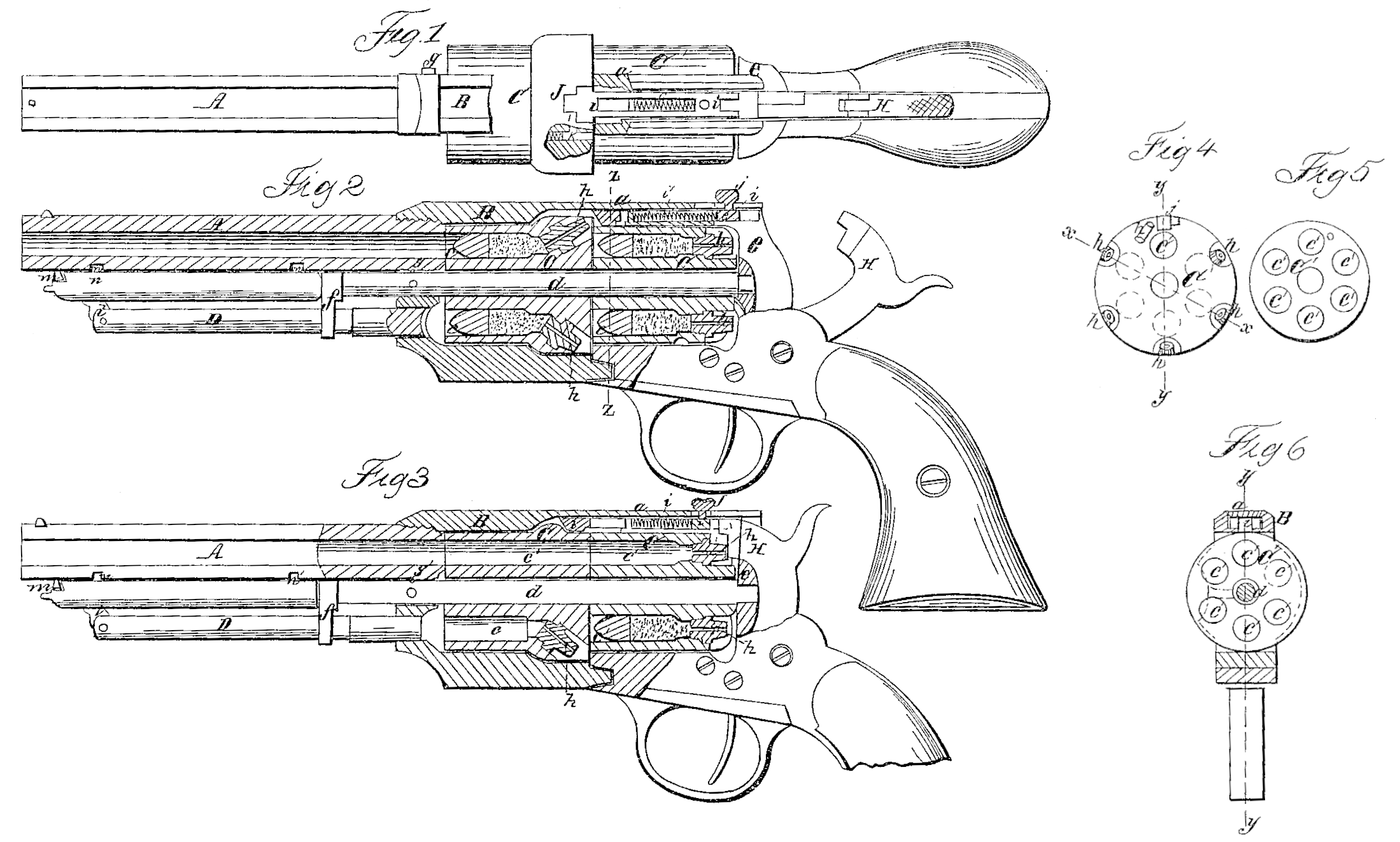
Figure l is a plan or top view of this invention, partly in section, showing the rear cylinder disengaged and the fire-arm arranged so that the rear cylinder can be fired. Fig. 2 is a longitudinal vertical central section of the same when both cylinders are loaded and arranged so as to fire the forward cylinder, the plane of section being indicated by the line x x, Fig. 4. Fig. 3 is a similar section when the front cylinder is discharged and the rear cylinder in position to be discharged, the lines y y, Figs. 4 and 6, indicating the plane of section. Fig. 4 is a rear elevation of the front cylinder. Fig. 5 is a front elevation of the rear cylinder. Fig. 6 is a transverse vertical section of the fire-arm, the plane of section being indicated by the line z z, Fig. 2, and looking in the direction of the arrow opposite to that line.
Similar letters of reference indicate like parts.
This invention consists in the employment or use of two or more cylinders, one behind the other, and arranged in such a manner that both are fired by one and the same lock and hammer, the charges in the first cylinder being fired first, and those in the rear cylinder afterward, or vice versa. During the time the front cylinder is being fired both cylinders are coupled together and rotated by the action of a dog connected to the hammer in the usual manner. The caps of the front cylinder are exploded by a slide which passes over the rear cylinder, and is so shaped that it prevents the hammer coming in contact with the caps of the rear cylinder. One chamber of the front cylinder is bored clear through, and, if it is desired to fire the charges of the rear cylinder, said open chamber of the front cylinder is brought in line with the barrel, and the slide is pushed forward and locked. By doing so the slide pushes back the pin which couples the two cylinders together, and enters a recess, so that the first cylinder is held stationary, while the rear cylinder is allowed to rotate and to be discharged in the usual manner. The ramrod is made of two parts and hinged together, so that it serves for both cylinders.
A represents the barrel of a revolver, which is connected to the frame B by means of a screw-thread, or in any other suitable manner. Said frame is made long enough to hold two cylinders, C C’, one in front of the other, and it is made in two parts, fitted together by a slide, a, so that the same can be drawn out in order to get access to the chambers c c’ in the two cylinders for the purpose of loading or for any other purpose. The two cylinders revolve on the common center-pin d, which is secured in the abutting-plate e by a set screw or any other suitable means, and from the front end of which extends an arm, f, which forms the guide for the ramrod D.
A spring-catch, g, arranged on the side of the frame B, and made to drop into a cavity or socket, g’, in the center-pin, locks the two parts of the frame together when the fire-arm is in condition for firing. By placing the hammer on half-cock and pressing on the button of the spring-catch g the two parts of the frame are uncoupled, and they can now be drawn out until the front end of said frame comes in contact with the arm fat the extreme end of the center-pin. If it is desired to take the cylinder entirely out, the set-screw in the abutting-plate has to be removed, so that the center pin can be withdrawn and the two parts of the frame can be separated.
The first cylinder, C, is provided with five ordinary chambers, c, and with one open chamber, c*, Figs. 3 and 4. Each of the ordinary chambers is provided with a nipple, h, to receive the percussion cap in the usual manner, and said caps are exploded by the action of the hammer H on a slide, i. This slide is fit ted into a recess in the frame B above the rear cylinder, and it is so constructed that when its tip or head strikes one of the nipples of the front cylinder the hammer His prevented coming in contact with the corresponding nipple of the rear cylinder; but if the open chamber c* of the front cylinder is brought in line with the bore of the barrel the head of the slide i drops into a recess, j, over said chamber, (see Fig. 1) and the hammer H is permitted to strike the nipples of the rear cylinder as the same present themselves in successive order. A small spiral spring, i’, forces the slide back after each stroke of the hammer while the front cylinder is being fired; but when the rear cylinder is being fired, and the slide is pushed into the recess i, said slide is locked by turning the button j’ in the enlarged portion of the guide-slot, in which it moves. This button is provided with notches, and it serves as a movable sight. During the time the front cylinder is being fired the two cylinders are coupled together by a spring-catch, k, which is inserted into a cavity in the front cylinder and drops into a corresponding socket in the rear cylinder. This spring-catch is situated in close proximity to the cavity j, (see Fig. 1) and it is provided with a nose, which projects out into this cavity, as shown in Fig. 4. When the two cylinders are coupled they rotate simultaneously, being propelled by a dog attached to the hammer and acting on teeth cut in the rear end of the rear cylinder in the usual manner, and the several chambers of the front cylinder are thereby brought opposite the slide i and discharged one after the other by the action the hammer H on said slide. When the slide i is pushed forward into the cavity i its lead strikes the nose of the spring-catch k and presses the same back, so as to disengage the two cylinders, as shown in Fig. 1. The front cylinder is thereby locked, having its open chamber c* in line with the barrel, and the rear cylinder is made to rotate independent of the front cylinder by the action of the hammer. By the action of moving the slide i forward the nipples of the rear cylinder are uncovered, and the hammer, in coming down, is allowed to explode the caps placed on the same. The charges in the several chambers of the rear cylinder are fired through the open chamber c* of the front cylinder, which in this case forms an elongation of the barrel.
In order to prevent the gases from dirtying the adjoining faces of the two cylinders, a small space might be left between the two cylinders and the open chamber c* made to extend back in the same manner as the barrel does to meet the chamber of the revolving cylinder.
The ramrod D of my fire-arm is made in two parts, which are connected by a hinge joint, l. When the ramrod is not used it is folded up, as shown in Figs. 2 and 3, and locked under the nose m at the under side of the barrel in the usual manner.
In order to load the front cylinder the ramrod is released from the nose m, and after the charge has been introduced in one of the chambers the end of the hinged portion of the ram rod is inserted into the upper or outer notch, m, in the under side of the barrel, and by using said hinged portion as a hand-lever the ramrod is depressed with sufficient power to drive the charge home. After all the chambers of the front cylinder are loaded the open chamber c* in said cylinder is brought opposite the ramrod, and then the frame is drawn out, and the charge is introduced into one of the chambers of the rear cylinder, one after the other, and rammed home. In driving the charges home in these chambers the end of the hinged portion of the ramrod is inserted into the inner notch, n’. By this arrangement all the chambers can be loaded With little trouble or loss of time and without taking the cylinders out of the frame.
It must be remarked, however, that the two cylinders, instead of being arranged as described, might be so constructed that their position could be changed, and that the rear cylinder could be brought in front either by turning both cylinders out and sliding one forward and the other back, or the cylinders might be made to face in opposite directions and to Swing on a pivot, so as to change their positions.
It will also be readily understood that the number of chambers on the several cylinders or the number of cylinders themselves might be increased to any desired extent.
The open chamber c* may also be so arranged that the barrel can be made to slide back, and that the rear cylinder can be fired in the ordinary manner.
Having thus described my invention, I claim as new and desire to secure by Letters Patent—
1. The employment or use of two or more cylinders presented in the same direction, one behind the other, and arranged in combination with one and the same hammer, substantially as and for the purpose set forth.
2. The slide i, applied in combination with the two cylinders C C’ and hammer H, constructed and operating substantially as and for the purpose described.
3. The spring-catch k., applied in combination with the two cylinders C C, and slide i, substantially as and for the purpose specified.
4. Firing the charges of the rear cylinder through the front cylinder, substantially as herein set forth.
5. The grooved-headed button j’ of the slide i, constructed and adapted to operate as a sight, as herein explained.
GEO. H. GARDNER.
Witnesses:
M. M. Livingston,
J. P. Haill.