
US 352863
UNITED STATES PATENT OFFICE.
GUSTAF ENVALL OF STOCKHOLM, SWEDEN, ASSIGNOR TO WILLIAM W. THOMAS, JR., OF PORTLAND, MAINE.
REVOLVER.
SPECIFICATION forming part of Letters Patent No. 352,863, dated November 16, 1886.
Application filed June 3, 1885. Serial No. 167,507. (No model.)
To all whom it may concern:
Be it known that I, GUSTAF ENVALL, Major in the Swedish Army, a subject of the King of Sweden, and a resident of Stockholm, Sweden, have invented certain Improvements in Mechanisms of Revolvers, of which the following is a specification.
In the automatically-cocking revolvers hitherto in use it has been necessary before taking aim to bring them to full-cock with the thumb, as in ordinary pistols, in order to insure a good aim. With rapid firing, however, when there is no time for cocking beforehand, the cocking must be done and the shot fired by a single pull of the forefinger. Under these circumstances the mainspring offers a great resistance, and the finger having to travel a distance of thirteen to fourteen millimeters the pull must be effected almost instantaneously, and a trembling of the weapon can scarcely be prevented. It is often remarked that at very short distances persons fire successively several times without making a hit or only occasioning a slight wound.
The object of this invention is the production of a lock mechanism affording greater accuracy, particularly in rapid firing, by the use of two triggers, one under the revolver, whereby the weapon is cocked, but by which it cannot be fired, and another at the top, whereby the shot is fired by the thumb. This mode of operation has the advantage that the revolver is not brought out of position at the very moment of firing.
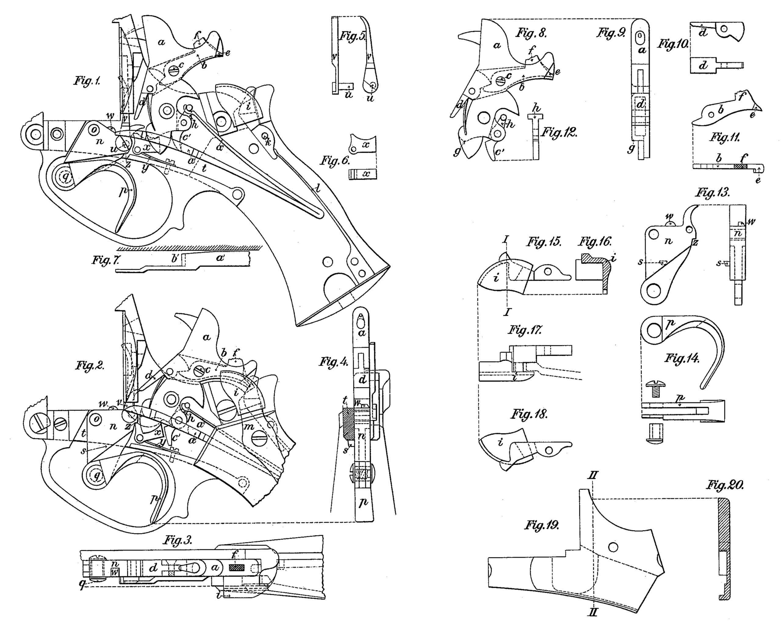
On the accompanying sheet of drawings, Figure 1 represents a side view of the lock and the rear part of the revolver, with the side plate and cheek taken away, the revolver being safety-cocked. Fig. 2 represents a side 4o view of the lock or the mechanism with the side plate removed, the hammer being brought to the full-cock. Fig. 3 is a plan. Fig. 4 is a cross section in front of the hammer a and the spanner n, showing them when brought to the full-cock. The other figures represent details of the mechanism. Fig. 5 represents, viewed from two sides, the pawl v, by which the revolver-drum is turned. Fig. 6 is a top view and a side view of the catch x. Fig. 7 is the 5o fore part of the undermost arm, a’, of the main spring, viewed from above. Fig. 8 represents 5 a side view of the hammer a, and Fig. 9 a front view of the sane. Figs. 10, 11; and 12, represent the movable parts of the hammer removed, viz: Fig. 10, the tongue d; Fig. 11, the lever b, each shown from two sides; and Fig. 12, a front view of the mainspring-link h. Fig. 13 is a front and side view of the spanner proper, n; and Fig. 14, a side and top view of the arm p of the spanner. Fig. 15 is a side view of the trigger i, seen from without. Fig. 16 is a section of the same along the line I I of Fig. 15. Fig. 17 is the same seen from above, and Fig. 18 the same from the inner side. Fig. 19 is a side view of the side plate, and Fig. 20 the same in section along the line II II of Fig. 19.
Similar letters of reference indicate corresponding parts in all the figures.
In this lock mechanism the hammer a is provided with a lever, b, passing through a hole in the hammer and pivoted at c. The shorter arm of this lever is situated below a backwardly-projecting tail of the tongue d. The longer arm is provided with a tappet, e, projecting from the end of the comb of the cock, and also with a projection, f, extending a little outside the inner rounding of the comb. The hammer is further provided with a shoulder or rounded surface, g, at the one side. So the mainspring-link h, embraced by the top arm, a”, of the mainspring, is extended downward.
The trigger i, situated at the top of the butt, is pivoted at k and actuated by the spring l, and kept in position by the downwardly-bent end of the plate m. (Shown by the dotted lines in Fig. 19.)
The spanner n, pivoted on the pin o, the arm p of which is pivoted thereon, is provided with a stop, s, which, by encountering a fixed part of the revolver-body t, limits its motion. On the spanner n is the pawl v, pivoted on its pin u, by which pawl the drum (not shown on the drawings) is turned around. w is a shoulder, which at the full-cock falls in a slot in the drum, thus fixing it.
x is a catch, which, actuated by a little spring, y, is pressed into the notch or slit z on the spanner when the hammer is brought to the full-cock.
The mechanism works in the following manner: In order to cock the hammer, the arm of the spanner is pulled back with the forefinger, (or the middle finger) whereby the spanner proper, n, turns on the pin o until the stop s encounters the lower edge of the revolver body, and the catch x is pressed into the slit z. The spanner n is now locked by the catch x and the stops, and the hammer has been brought to the full-cock, as shown in Fig. 2. The pawl v has meanwhile turned the drum the requisite angle, and the shoulder w of the spanner fixes the drum in the usual manner. Now, a sure aim being taken, the firing is effected by pressing the trigger i downward by means of the thumb. The trigger actuates then the lever b, and this turns the tongue d from its support against the spanner n, and the upper arm, a”, of the mainspring causes the hammer to fall down. On falling, the shoulder g on the hammer presses the catch x out of the slit z of the spanner n, which becomes free. When the shot has been fired, but not before, the forefinger yields, when the bottom arm, a’, of the main spring, reposing upon the pawl v, brings back the spanner into its former position. (See Fig. 1.) At the same time the shoulder b’ of the mainspring arm a’ glides along the curved surface c of the downwardly-extending part of the mainspring-link h, and presses the hammer to the safety-bend. (Shown in Fig. 1.)
If, after cocking, the shot is not to be fired, the hammer may be let down in the usual manner with the thumb by pressing in the projection f. The hammer moves then automatically into the safety position.
I claim as my invention–
1. The combination of the stock and hammer of a revolver, with a firing trigger on the top of the stock to be pressed by the thumb, and a spanner-trigger below the hammer to cock the latter, and having a stop, s, to come into contact with the stock when the hammer is brought to the full-cock, substantially as set forth.
2. The combination of the stock and hammer of a revolver, and the cocking-spanner pivoted to the stock, with a movable tongue, d, on the hammer, with which the said spanner engages, and a lever, b, also on the hammer, engaging with said movable tongue, as and for the purpose specified.
3. The combination of the stock and hammer of a revolver, and a firing-trigger on top of the stock, with a cocking-spanner below, having a notch, z, and a catch, x, to engage with and retain the spanner, the said hammer having a shoulder, g, to act on the catch and release the spanner when the revolver is fired, substantially as described.
4. The combination of the hammer of a revolver, having a shoulder, g, at its lower end, with a movable tongue, d, and a lever, b, both carried by the hammer, a firing-trigger pivoted to the stock and engaging with said lever b, the cocking-spanner n, a catch, x, engaging with the spanner, and a spring, a’ a”, bearing on the hammer and spanner, substantially as set forth.
In testimony whereof I have signed my name to this specification in the presence of two subscribing witnesses.
GUSTAF ENVALL.
Witnesses:
NERE A. ELFWING,
FREDRIK L. ENQUIST.