
US 41117
Be it known that we, H. A. BRIGGs and
SAMUEL S. HoPKINS, both of Norwich, in the county of New London and State of Connecticut, have invented certain new and useful Improvements in Revolving Fire-Arms; and we
do hereby declare that the following is a full, clear, and exact description of the same, reference being had to the accompanying drawings, forming part of this specification, in which
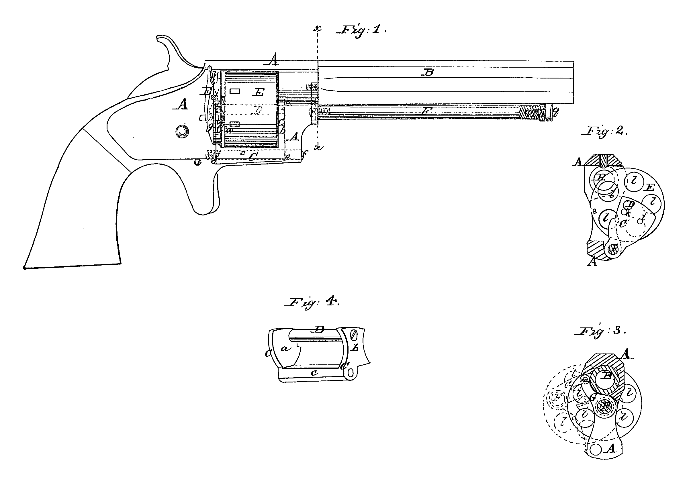
Figure 1 is a side view of a pistol with our
improvements. Fig. 2 is a transverse section
of the same in rear of the cylinder, showing
the cylinder in position for loading. Fig. 3 is
a transverse section of the same in the plane
indicated by the linea a in Fig. 1. Fig. 4 is
a perspective view of the swinging frame, in
which the cylinder axis-pin is supported.
Similar letters of reference indicate corresponding parts in the several figures,
In revolving-cylinder fire-arms which load
at the rear of the cylinder there have been
many different constructions of the frane and
modes of applying the cylinder to provide for
loading. One mode of applying the cylinder
which admits of a very simple construction of
the arm is to attach its axis-pin to a swinging
support, which permits the cylinder to swing
outward from the other parts of the arm in a
lateral direction; but as the said pin has only
been attached at one end to such support the
attachment has not been sufficiently firm or
durable. The object of the first part of this
invention is to afford a better support for and
more durable attachment of a so applied cyl
inder; and to this end it consists in the em
ployment within the main frame of the arm
of a laterally-swinging frame constructed to
support both ends of the axis-pin and to fit
within recesses in the main frame.
. The second part of the invention consists in
a novel mode of applying a plunger, in combi
nation with a cylinder having such a swinging
movement asis above specified, for thepurpose
of expelling the discharged cartridge – shells
from and cleaning the chambers, whereby,
while remaining attached to the arm, the said
plunger is permitted to have the necessary
movements for the purpose, and when not in
use is permitted to lie close under the station
ary barrel out of the way.
To enable others skilled in the art to make
and use our invention, we will proceed to de
scribe its construction and opt ration.
A is the main frame of the arm, of a form:
substantially like the frame of many other re
Wolving fire-arms, and made all of one piece.
B is the stationary barrel, screwed into or
otherwise secured to the frame A.
C is the swinging inner frame, which consti
tutes the principal feature of our invention.
The side view of this frame presents the form
of three sides of a parallelogram, the opposite
sides or ends having just space enough be
tween them to admit the cylinderendwise, and
being fitted into recesses de, provided for their
reception within the opening of the main frame
A, and the third side, c, being bored longitudi
nally for the reception of a pin, f, which passes
through it and through the lower past of the
front of the main fame A, and screws into the
back of the said frame, the said pin being par
allel with the bore of the stationary barrel
and near the right-hand side of the frame A.
ID is the cylinder axis-pin, passing through
and fitting snugly within a hole in the front
end, b, of the swinging frame, and being se.
cured tightly into the rear end, a, thereof, and
being parallel with the pinf. The cylinder E
is fitted to turn freely on this pin. The ends
a and b of the swinging frame and the recesses
de in the main frame which receive them are
so formed that in e, as the swinging frame
swings into the main frame, it is stopped’.in
such a position that the axis-pin D is directly
below the axis of the barrel, and that the cham
bers of the cylinder may by the revolution of
the cylinder on the said pin be brought one
at a time opposite to and in line with the bore
of the barrel; and there is provided in the re
coil-shield g, which forms part of the main
frame A, a spring-stop, h, which locks the
swinging frame in the above-mentioned posi.
tion by entering a hole, i, in the rear end of the
said frame. This stop is attached to a short
lever, E, which works on a fixed fulcrum, i,
and which has applied to it a spring, k, which operates to press the stoph forward, the said
lever being so arranged on the right-hand side
of the frame A that it can be operated to draw
back the stop and unlock the swinging frame
by the pressure of the thumb, while the arm
is grasped in the usual manner in the right
hand. There is another hole, k, in the rear
end of the swinging frame to receive the stop
i, and enable the said stop to lock the frame
in the position shown in Fig.2 and in red out
line in Fig. 3, to which it is moved outward
from the right side of the main frame to ex
pose the open rear ends of the chambers for
loading and for the expulsion of the exploded
cartridge-shells. A fixed stop may also be ap
plied to prevent the swinging out of the swing
ing frame and cylinder lueyond the last-men
tioned position.
The swinging frame, constructed as alove
described, having a long bearing on the pinf,
which issupported at both ends, is very strongly
attached to the main frame, and the axis-pin
D, being supported at both ends in the said
fame, makes a very steady and firm bearing
for the cylinder, whether the swinging frame
is in position for firing or for loading, and no
strain to wbich the parts are subject in the
operation of the arm will be liable to displace
or injure the axis-pin.
F is the plunger for expellingthe discharged
cartridge-shelks from thechambers ll of the cyl
inder, fitted to slide freely through a hole in a
link, G, which is pivoted by a pin, m, to the
front of the fraine A, on the right side of the
barrel, in such manner as to be capable of
swinging outward laterally from the barrel,
but which, when the plunger is not in use, lies.
snugly within a recess, n, provided for its re
ception in the front of the frame A, the plun
ger being at that time directly under the bar
rel, as shown in Fig. 1 and in black outline in
Fig. 3, where it is held by two small spring
bolts fitted one into each end, the one, p, en
tering a hole in a fixed stud, q, tander the muzzle of the barrel, and the other, r, enter
ing a lole in the front of the frame. These
spring-bolts have their points rounded, so that
they may slip easily into and out of their re
spective holes, above mentioned. When the
cylinder is to be reloaded it is first brought .
to the position shown in Fig.2 and in red out
line in Fig. 3, alld the plunger is pushed out
from under the cylinder, still attaclhed to the
link G, which swings outward from the main
frame till it (the plunger) comes to a position
shown in red outline in Fig. 3 to enter a cham
ber of the cylinder, the rear end of which is
clear of the recoil – shield. By pushing the
plunger through the link G and into the cham
ber thecartridge-shell is expelled,and by draw
ing forward the plunger again the cylinder is
permitted to be turned on its axis by hand to
present the next chamber in position to receive
the plunger, and by a repetition of the above
operation the exploded shells are expelled from
all the chambers, one after the other, and the
cylinder is ready for reloading.
What I claim as my invention, and desire to
secure by Letters Patent, is
1. The laterally – swinging frame lhaving a
bearing on a long pin, f, which extends from .
the front to the back of the main frame A, and
supporting the cylinder axis-pin both in front
and in rear of the cylinder and otherwise ap
plied, in combination with the main frame A,
substantially as and for the purpose herein
specified.
2. The plunger F, applied in combination
with the laterally – swiriging link and with a .
cylinder which is arranged to swing laterally
out of the main frame, substantially as and for
the purpose herein specified.