
US 501566
UNITED STATES PATENT OFFICE.
HUBERT HENRY GRENFELL, OF LONDON, AND JAMES GEORGE ACCLES, OF BIRMINGHAM, ENGLAND.
REVOLVING SMALL-ARM.
SPECIFICATION forming part of Letters Patent No. 501,566, dated July 18, 1893.
Application filed December 19, 1891, Serial No. 415,679. (No model.)
To all whom it may concern:
Be it known that we, HUBERT HENRY GRENFELL, captain in the Royal Navy, a subject of the Queen of Great Britain, and a resident of London, and JAMES GEORGE ACCLES, engineer, a citizen of the United States of America, residing at Birmingham, England, have invented certain new and useful Improvements in Revolving Small-Arms, of which the following is a specification, reference being had to the accompanying drawings.
The objects of our invention are chiefly to improve revolving pistols in respect to simplicity and durability of the mechanism. For this purpose we provided the weapon with a firing pin or plunger which has a rectilinear action, that is to say, its striking portion is a straight piece and moves in a straight line to and away from the cartridges in the cylinder under the action of a hammer or equivalent device. And we further provide the weapon with a cylinder stop operated by the trigger.
These improvements are hereinafter described with reference to the accompanying drawings, which relates to a revolving pistol constructed according to our invention.
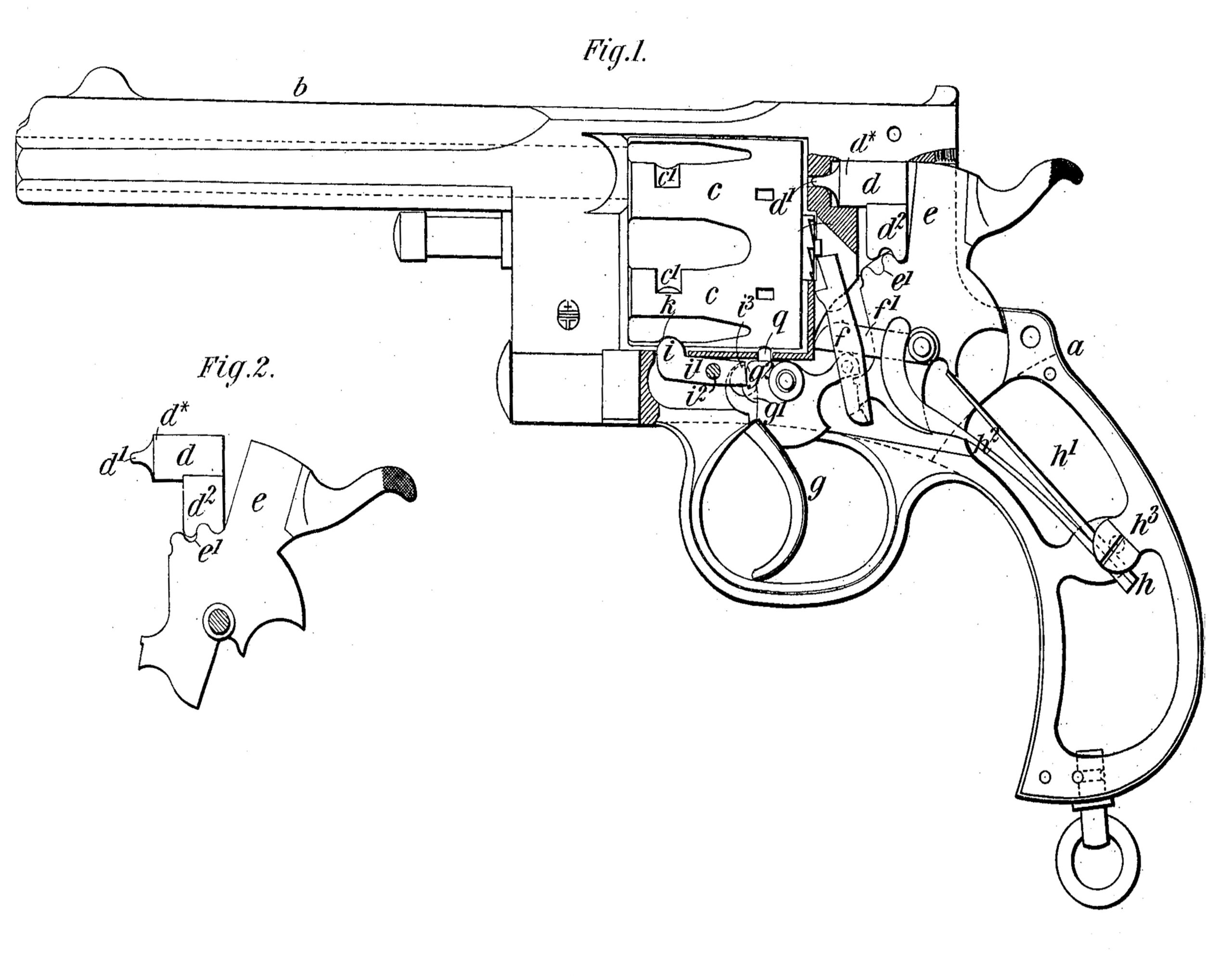
Figure 1 is a side view of the revolver, partly in longitudinal section. Fig. 2 is a side view of the firing pin and hammer.
Like letters indicate the same parts throughout the drawings.
a is the breech shoe or frame.
b is the barrel.
c is the cylinder.
d is the firing pin.
e is the hammer.
f is the lifter or arm for acting on the ratchet of the cylinder to rotate the same.
g is the trigger.
h is the main spring.
i is the aforesaid cylinder stop.
The striking portion dx of the pin or plunger is preferably made cylindrical in transverse section and has a suitably formed pivot or nose d’ at its extremity; it has extending down from its underside a toothed projection d2 which is arranged in combination and gears with a toothed portion e’ of the hammer e.
In cocking the hammer e, the teeth thereon acting on the teeth of the pin or plunger d will move the same back, and when the trigger is pulled the hammer, through the medium of the teeth will drive the said plunger forward and will finally impact thereon. We may use a hammer or its equivalent with a lever at the side of the pistol or with other convenient means for pulling it back.
The aforesaid cylinder stop is a nose or projection i on the forward end of a small arm i’ pivoted at i2 to the frame a below the cylinder, the said nose being arranged in combination with notches or recesses c’ in the said cylinder. There is a small projection g’ on the forward edge of the trigger g and when the trigger is at rest the rear end of said arm i’ engages with this projection and the stop i is then held out of the notches c’. The rear end i3 of the lever i’ and the part g2 of the trigger are so formed and arranged that when the trigger is pulled the rear end of the arm is thereby lowered and the nose or stop 2 is pressed up toward the periphery of the cylinder; therefore in the rotation of the cylinder about its axis, as each notch c’ comes opposite the said stop i the latter enters the notch and acting in combination with the lever or lifter f (which engages with the ratchet of the cylinder when the trigger is pulled) holds the said cylinder rigidly and immovably at the moment when the firing pin strikes the cartridge. The said nose or stop i projects through a slot k in a part of the frame a which forms a very firm lateral support to the said stop when engaging with the cylinder. We prefer to use a main spring formed of two separate pieces of steel; one of these parts h’ bears on the hammer and the other part h2 engages with the arm f’ that operates the lifter f, both parts being united at their fixed ends in a recess or notch at h3 in the butt or handle of the weapon as is clearly shown in Fig. 1.
The ordinary cylinder holder or locking pin is shown at o. We use said holder or locking pin for its ordinary purpose, in combination with our improvements.
It is obvious that the rectilinearly acting firing pin and the auxiliary cylinder stop may be applied or adapted to revolving fire arms of various kinds.
We claim as our invention—
1. In a revolver the combination of a firing pin provided with a downwardly projecting lug having teeth at its lower end, and a hammer adapted to strike the firing pin and provided with teeth e’ meshing with the teeth on the lug of the firing pin, substantially as described.
2. n a revolver, the combination of a firing pin d provided with a downwardly projecting lug having teeth, a hammer adapted to strike the firing pin, said hammer being provided with a toothed portion e’ meshing with the teeth on the firing pin, a stop lever i’, and a trigger connecting said stop lever and hammer for operating the same, substantially as described.
In testimony whereof we have hereunto signed our names in the presence of two subscribing witnesses.
HUBERT HENRY GRENFELL.
JAMES GEORGE ACCLES.
Witnesses:
JNO. FREDK. PARKES,
ERNEST HARKEN.