
US 33836
UNITED STATES PATENT OFFICE.
HENRY GROSS, OF TIFFIN, OHIO.
IMPROVEMENT IN REVOLVING FIRE-ARMS.
Specification forming part of Letters Patent No. 33, 836, dated December 3, 1861.
To all whom it may concern:
Be it known that I, Henry Gross, of Tiffin, in the county of Seneca and State of Ohio, have invented certain new and useful Improvements in Revolving Fire-Arms; and I do hereby declare that the following is a full, clear, and exact description of the construction and operation of the same, reference being had to the annexed drawings, making a part of this specification, in which—
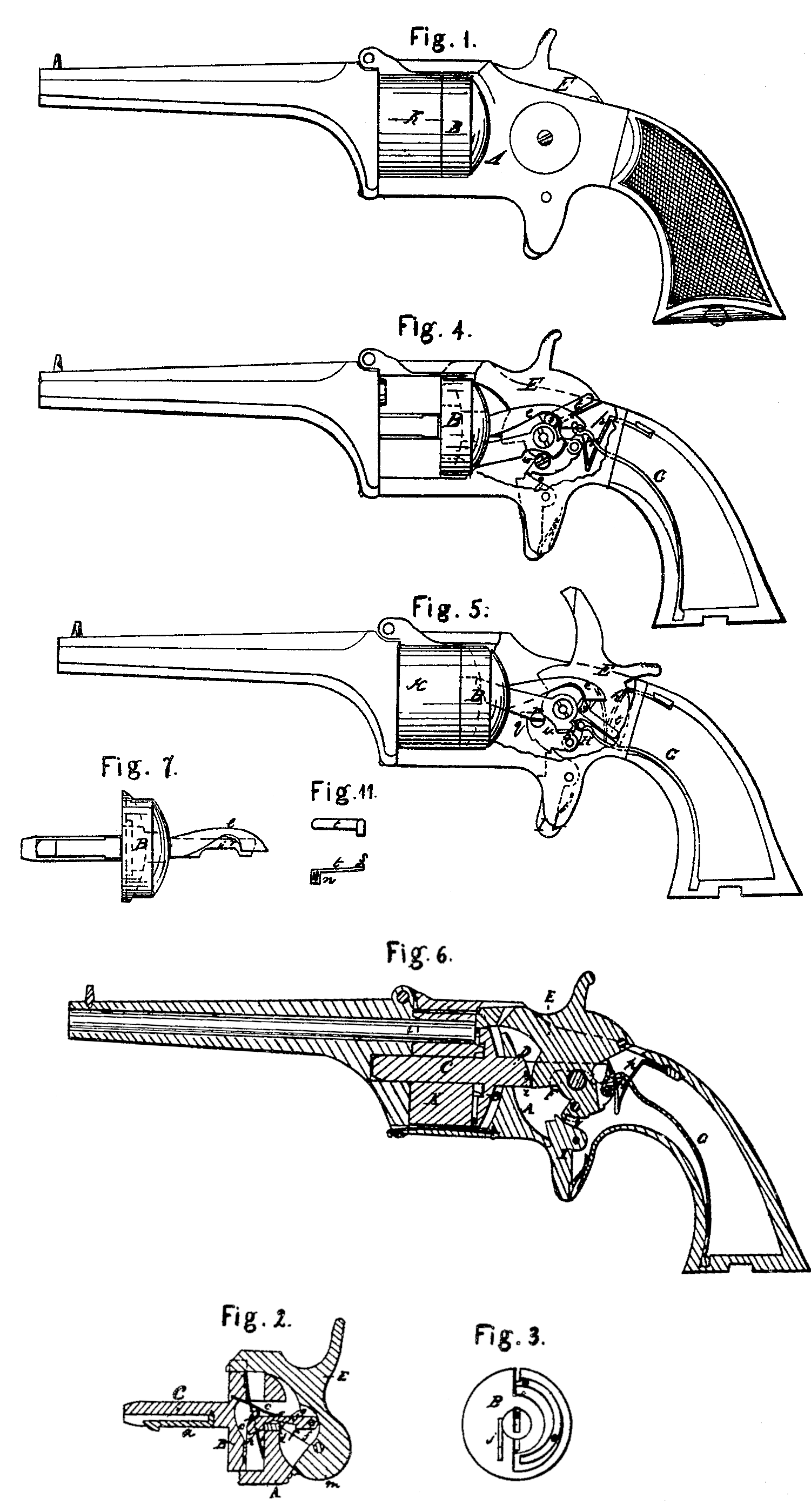
Figure 1 is a side view; Fig.2, a vertical section of the lock; Fig. 3, an inner face view of the movable recoil-plate, showing the springs; Fig. 4, a side view with the side plate removed, showing the position of the mechanism when the cock is down, which mechanism is a modification of that shown in Fig. 2. Fig. 5 is a like view, showing the position of the same parts when the cock is up. Fig. 6 is a longitudinal section of the modified arm, showing the method in which the cock locks the cylinder. Figs. 7 and S are side and top views of the movable recoil-plate of the same arm, with its adjuncts. Fig. 9 is an end view of the same. Fig. 10 represents different views of its dog for rotating the cylinder, and Fig. 11 a face and side view of the spring-cam.
The object of my invention is the production of a revolver in which the breech of the barrel may enter a short distance into the several bores of the cylinder preparatory to each discharge, and be withdrawn therefrom after each discharge by the retraction of the cylinder; and the nature of it consists in the peculiar construction and arrangement of the lock, whereby not only is the cylinder withdrawn from the breech of the barrel, rotated, and released, so that it may automatically return to its normal position by the raising of the cock or hammer, but by which, also, the cylinder is firmly locked against the breech of the barrel at the instant of the discharge.
To enable others skilled in the art to make and use my invention, I will proceed to describe its construction and operation.
The stationary recoil-plate A, Figs 2 and 6, is, in conjunction with the top and bottom straps of the stock, fitted to receive a movable recoil-plate, B, provided on each face and at right angles thereto with a journal or shaft, the front one, C, being that whereon revolves the cylinder K, and the rear one, D, being that which passes through a hole in the stationary recoil-plate, and serves as a guide in the horizontal movements of the movable recoil-plate and the cylinder. The former of these journals does not differ in its functions from those usually found in this class of fire-arms, except that it has a horizontal motion back and forth, and carries with it in such movement the cylinder, which is fixed thereto by means of the spring-detent, a, Fig. 2; but the latter journal— viz., D— is mortised or slotted vertically through, as seen at c, Fig. 2, a small bar-like portion, d, only being left therein across its lower rear end. The same construction is shown in Figs. 7 and 8, except that the bar d in the fork or slot c is dispensed with, and its office performed by the hooked prong e.
The cock or hammer E, Figs, 2 and 6, is, in front of its center of motion, formed with a cam, F, the elevated portion of which in Fig. 2 is slotted vertically and receives a hinged hook, g, whose front end has a cam-like formation or beveled edge, h; or, as in Figs. 7 and 8, the prongs e and i may pass either side of or embrace the cam F.
The movable (as also the stationary) recoil-plate B is mortised or cut through, in which slot plays a dog, this dog being hinged to the extension of the cock below its center of motion in a position not shown in Fig. 2, but which maybe indicated by the letter m therein. The dog is held down upon the bottom of the cuts through the stationary and movable recoil-plates by means of a spring pressing upon its upper surface; but as it (the dog) is impelled forward against the teeth of the ratchet-wheel on the rear end of the cylinder it is elevated against the power of the spring and thus kept in gear until the discharge takes place, when the dog is retracted for another advance. Instead of the dog thus described, that represented in Fig. 10 may be employed, which, as shown in Figs. 4 and 5, has a common center of motion with the cock itself. In this case, in order to impart the proper motion to the dog it has a cam-like formation near its eye or pivotal point, as seen at w, in which plays the head of the screw n. As the cock plays back and forth a positive up and down notion is imparted by this arrangement to the dog instead of a variable one, as secured by the spring. The movable recoil-plate B is furnished with a circular spring, o, Figs. 2 and 3, bearing against the stationary recoil-plate A; or a bent spring may be employed to press against the end of the prong i of the fork c, Figs. G and 8, as represented at p, Figs. 4 and 6, and in dotted lines in Fig. 5.
G is the mainspring, attached in the ordinary manner to the cock or tumbler by means of the swivel H.
I is the trigger, which, when the cock is slightly raised from off the cap, engages with the first ratchet-tooth, q, of the tumbler, which is so formed that while thus engaged the charge cannot be exploded by means of the hammer.
In regard to the manner of operating the modified movable recoil-plate represented in Figs. 4, 5, 6, 7, and 8, it must be observed that the hooked prong e of the fork c’ is beveled on its inner surface in such a manner as to allow it to slide back over the spring-cam s, Figs. 4 and 5, as the cock descends, the cam itself being so formed as to favor this operation— i. e., being also beveled, and being capable of being sprung back out of the way until the cock has descended and exploded the charge— when again the spring-cam approaches and is ready for another engagement with the hooked prong e. The precise shape of this spring-cam may be determined on reference to Fig. 11, it being necessary only to observe further that it is let into the face of the tumbler, as shown at t, Figs. 4 and 5, by means of its shank u, Fig. 11.
The operation of this my improved revolving fire-arm is as follows, referring first to Fig. 2: The cock is there represented as down, and the discharge just to have taken place. The thumb is affixed to the thumb-piece, and as the hammer is raised the hinged hook g draws back the movable recoil-plate and cylinder, the cam-shaped end or beveled edge h of the said hook at the same time gliding over the bottom of the hole through the stationary recoil-plate, and being thus gradually elevated out of contact with the front edge of the bar d until the breech v of the barrel is released from the bore of the cylinder, when the dog comes into contact with the ratchet-wheel of the cylinder and gives said cylinder the requisite turn. Precisely at this point of time the hook g is raised out of contact with the front edge of the bar d and rests upon its upper surface, and the spring o forces the movable recoil-plate and cylinder forward into contact with the breech of the barrel, as represented at v, Fig. 6. The lock is now fully cocked. On pulling the trigger the hammer descends, and at the same instant the cam F is brought into contact with the rear end of journal or shaft D, as represented at d, Fig. 2, and the barrel and cylinder are firmly locked together.
The action of the mechanism shown in Figs. 4 and 5 is entirely analogous, with the exception that the cam F at the moment of the discharge rests against the heel of the fork c’, as shown at 2, Figs. 6 and 8, the action of the spring-cams being sufficiently explained above.
Having thus described my invention and illustrated its operation, as well as explained its principle and the several modes in which I have contemplated the application of that principle, what I claim as of my invention, and desire to secure by Letters Patent of the United States, is—
The hammer E, when constructed as described, which, on being raised or cocked, through the mechanism described, withdraws the cylinder from the breech of the barrel, intermittently revolves and releases it, and by means of its projecting part or cam F firmly locks the cylinder to the barrel at the moment of firing, as set forth.
HENRY GROSS.
Witnesses:
James Graves,
J. B. Woodruff.