
US 408457
UNITED STATES PATENT OFFICE.
HOMER M. CALDWELL, OF WORCESTER, MASSACHUSETTS, ASSIGNOR TO THE HARRINGTON & RICHARDSON ARMS COMPANY, OF SAME. PLACE.
REVOLVING FIRE-ARM.
SPECIFICATION forming part of Letters Patent No. 408,457, dated August 6, 1889.
Application filed March 25, 1889. Serial No. 304,615. (No model.)
To all whom it may concern:
Be it known that I, HOMER M. CALDWELL, a citizen of the United States, residing at Worcester, in the county of Worcester and State of Massachusetts, have invented certain new and useful Improvements in Revolving Fire Arms, of which the following, together with the accompanying drawings, is a specification sufficiently full, clear, and exact to enable persons skilled in the art to which this invention
appertains to make and use the same.
My present invention relates to the peculiar construction and manner of arranging the cylinder-actuating hand or finger and its spring, in combination with the hammer-lifter and trigger, the object being to afford a construction adapted for narrow frames and in which the pivoting-joints are so disposed as to be kept within the frame limit when the trigger is forward; also, to render both the hand and lifter operative by one and the same spring, as hereinafter explained.
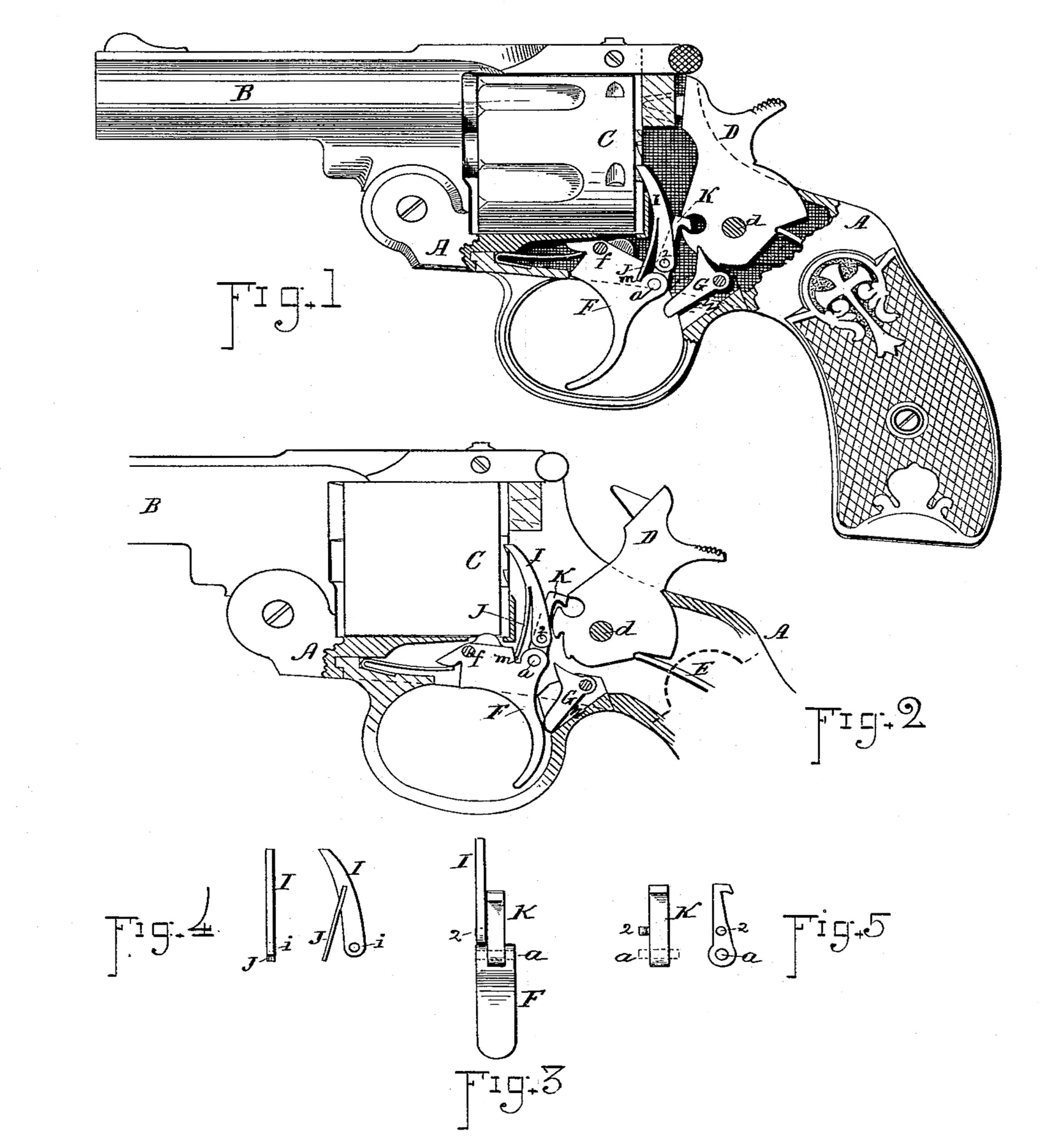
These objects I attain by the mechanism illustrated and described, the particular subject-matter claimed being hereinafter definitely specified. In the drawings, Figure 1 is a view of a revolver, showing the side of my improved mechanism, the parts being in normal position. Fig. 2 is a side view of the mechanism with the hammer raised and at the point of discharge. Fig. 3 is a rear view of the trigger with the lifter and hand thereon. Fig. 4 shows a rear and side view of the hand separate, and Fig. 5 shows a side and rear view of the lifter.
In reference to parts, A denotes the frame, B the barrel, C the cylinder, D the hammer, and E. the mainspring, which parts may all be arranged substantially as. heretofore employed.
F indicates the trigger; G, the sear; I, the cylinder-actuating finger or hand; and K, the lifter or actuating-pawl, by which the hammer is elevated and discharged when the trigger is pressed backward. The trigger F is pivoted at f, and the hammer D is pivoted at d to swing back in the usual well-known manner. The lifter K is hinged or pivoted on the top of the trigger, as at a, and is provided with a backwardly-extended top end that engages within a recess in the front of the hammer, as indicated. In accordance with my invention the lifter K is provided with a stud 2 on its side, preferably formed integral therewith and at a position about one-third (more or less) of the length of the lifter-arm above the hinging-axis a, which is located at the extreme upper rear corner of the trigger-head, and the heel end of the hand or cylinder-actuating finger I is fitted with a suitable hole i, that fits over the pivot 2, whereby said hand is supported or fulcrumed on said lifter-arm, as shown. A spring J has its upper end fixed in the front of the hand-lever I, while the lower end of said spring engages in a notch m, formed in the top of the trigger, just forward of the lifter-hinge a. The action of this spring is by leverage over the pivot 2 as a fulcrum, and it serves to press forward the top end of the hand and keep it in proper engagement with the ratchets on the end of cylinder C, while at the same time a backward pressure is exerted at the heel end of the hand-lever and against the stud 2. Consequently the lifter is thereby pressed backward into the recess of the hammer while the parts are being raised by the backward movement of the trigger, thus obviating any liability of the lifter slipping from the notch or recess before the hammer has reached its full elevation. The spring action is operative at all times,
both to throw back the lifter and to throw forward the hand, and this, too, without giving resistance against the backward movement of the trigger.
The advantages of this construction are that the parts can be easily made, a flat straight spring without side projection is used, and the arrangement of the spring is such as to give freedom of action for the lifter and hand.
While I prefer to arrange the spring with its top end fixed to the hand, it is obvious that it can be reversely attached or fixed on the trigger to effect equivalent action—viz., to give forward pressure at the top end and backward pressure at the lower end of the hand-lever.
I claim as my invention to be secured by Letters Patent—
1. The hand I and spring J, said spring being attached to the hand and extending downward in front of the same to a point below its hinging-axis, in combination with the cylinder-ratchet, the hammer-lifter, and the trigger carrying the lifter-hinge at its upper rear corner, and provided with a notch in front of the lifter-hinge, into which the end of said spring engages, all substantially as and for the purpose set forth.
2. In a revolver, the combination, substantially as described, of the trigger having the notch m in its top, the hammer-lifter hinged to said trigger, as shown, and provided with the laterally-projecting integral stud 2 on its side, the hand pivoted on said stud and engaging the cylinder-ratchet, and the flat spring disposed in front of said hand with its lower end supported in the notch on the top of the trigger, said spring being strained in a manner to press the engaging end of the hand toward
the ratchet and to force backward its pivot end together with the lifter, as and for the
purpose set forth.
Witness my hand this 20th day of March, A. D. 1889.
HOMER M. CALDWELL.
Witnesses:
CHAS. H. BURLEIGH,
ELLA P. BLENUS.