
US 38921
UNITED STATES PATENT OFFICE.
HORACE SMITH AND D. B. WESSON, OF SPRINGFIELD, MASSACEUSETTS.
IMPROVEMENT IN REVOLVING FIRE-ARMS.
Specification forming part of Letters Patent No. 3S,921, dated June 16, 1863,
To all whom it may concern:
Be it known that we, Horace Smith and D. B. Wesson, of Springfield, in the county of Hampden and State of Massachusetts, have invented a new and useful Improvement in Revolving Fire-Arms; and we do hereby declare that the following is a full, clear, and exact description of the same, reference being had to the accompanying drawings, forming a part of this specification, in which—
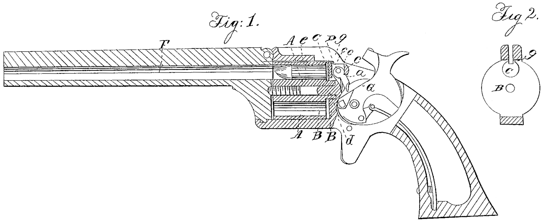
Figure 1 is a longitudinal vertical section of a pistol with our improvement; Fig. 2, a front view of the recoil-shield.
Similar letters of reference indicate corresponding parts in the several figures.
Our invention relates to that class of revolving fire-arms which have the chambers extended right through the cylinder for loading from the rear. The metallic shells or cases of the cartridges commonly used in such arms are made to protrude a short distance from the rear end of the cylinder, and the flanged parts so protruding are frequently so expanded by the explosion of the charge as to cause them to bind between the cylinder and the recoil-shield and make the cylinder revolve very hard.
The object of our improvement is to prevent this binding of the cartridge-shell, and so insure the easy revolution of the cylinder; and to this end it consists in fitting the recoil-shield with a sliding breech-pin arranged opposite to and in line with the barrel, and so operated by the lock as to move forward as the hammer falls to strike for the purpose of supporting the cartridge, which is brought in line with the barrel, and of holding the said cartridge in place at the time of firing, and to move back again and leave the shell of the said cartridge free as the hammer is recocked.
To enable others skilled in the art to make and use our invention, we will proceed to describe its construction and operation.
A is the cylinder, B the recoil-shield, and F the barrel.
C is the movable breech – pin, which constitutes our invention, fitted to slide freely back and forth as far as necessary in a direction parallel with the bores of the barrel and chambers, in a position directly opposite the barrel. This pin has its front end or head as large, or nearly as large, in diameter as the rear ends of the cartridge-shells e, but has a notch, g, in its upper part for the passage of the nose of the hammer G to strike the cartridge.
a is a pin screwed or otherwise securely inserted into the recoil-shield in a transverse direction, and passing through a hole in the breech-pin C, such hole being slightly elongated in a backward and forward direction, as shown in dotted outline in Fig.1, to permit the slight backward and forward movement which is necessary to the breech-pin. This pin a constitutes the fulcrum of a small lever, D, the bend of which is formed like an eccentric or cam, as shown in Fig. 1, and is fitted within a vertical slot, c, provided in the breech-pin for its reception. This lever D has applied to it a spring, d, which tends to press back its lower end, and so turn its cam-like or eccentric head in a direction to draw back the breech-pin and bring the head thereof flush with the face of the recoil-shield. The lower part of the said lever is so arranged as to be acted upon by the hammer G as by a cam, while the latter is falling or moving forward to strike in such a manner as to turn the cam-like or eccentric head in a direction to push forward the breech-pin and cause the protrusion of the head of the latter far enough through the face of the recoil-shield to enable it to support the rear end of the cartridge, which is brought opposite to and in line with the barrel by the revolution of the cylinder, and hold the said cartridge in place at the time of firing, the space left between the cylinder and the recoil-shield being slightly greater than the thickness of the flanges of the cartridges. As the hammer is drawn back to recock it and produce the necessary revolution of the cylinder the spring d pushes back the lower end of the lever and causes its cam-like head to draw back the breech-pin, so that it will offer no obstruction to the revolution of the cylinder. This movement of the breech-pin back and forth does not require to be greater than the distance shown in Fig. 1. between the cartridge-shell e and the said pin, which is represented in that view as drawn back, the hammer being cocked.
Instead of employing a spring, d, to throw back the lever D, a notch may be so provided in the hammer as to receive the end of the said lever and cause the latter to be drawn back by the hammer in cocking.
What we claim as our invention, and desire to secure by Letters Patent, is—
The movable breech-pin C, applied in combination with the revolving cylinder having its chambers extended through its rear, to operate substantially as and for the purpose herein specified.
HORACE SMITH,
D. B. WESSON.
Witnesses:
C. E. Buckland,
Joseph M. Hall.