
US 24666
UNITED STATES PATENT OFFICE.
HORACE SMITH AND D. B. WESSON, OF SPRINGFIELD, MASSACEUSETTS,
IMPROVEMENT IN REVOLVING FIRE-ARMS.
Specification forming part of Letters Patent No. 24,666, dated July 5, 1859.
To all whom it may concern:
Be it known that we, Horace Smith and Daniel B. Wesson, both of Springfield, in the county of Hampden and Commonwealth of Massachusetts, have invented a new and useful Improvement in Revolving Fire-Arms; and we do hereby declare that the following is a full, clear, and exact description of the construction and operation of the same, reference being had to the accompanying drawings, making a part of this specification, in which—
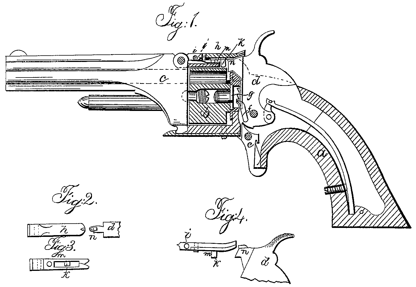
Figure 1 is a partial section of one of our pistols with the improvement attached; Figs. 2, 3, and 4, views of the improvement detached from the rest of the pistol.
Like letters of reference indicate the same parts in each of the figures.
In all fire-arms with revolving cylinders it is necessary to provide a stop for the cylinder to hold it firmly in its place while the charge is being ignited in order to insure the entrance of the ball into the barrel; and it is furthermore necessary that this stop shall be entirely released from the cylinder before it commences to revolve, and that the stop shall be at liberty to take effect on the cylinder and hold it constantly in its proper situation from the time the cylinder ceases revolving till after the charge has been ignited.
It is the object of this invention to furnish such a stop which shall be simple, durable, and entirely separated from the lock of the pistol, thereby simplifying the lock and placing the stop in such a position that it can be detached for repairs or other purposes without interfering with the lock.
In the accompanying drawings, Fig. 1, a is the lock-frame; b, the cylinder for holding the charges; c, the barrel; d, the hammer, and e the trigger, f is the pawl and g the ratchet, by means of which the cylinder is revolved. l is the “stop,” (seen in detail in Figs. 2, 3, and 4,) which is composed of a small lever or finger pivoted at i and having a projection, k, which we call the “stop-bolt,” on its under side, which projection or bolt enters corresponding cavities or notches in the periphery of the cylinder b and holds it in its proper position, the bolt being held down by the spring l bearing upon the lever h back of pin i. On the under side of h is a split spring, m, (seen in Fig. 3,) the split ends being beveled in such a manner as to allow a wedge-shaped body to enter, and, separating the springs, to pass through, the spring closing after it. Now, on the top of the nose of the hammer we place such a wedge-shaped projection, n, the sharp end of the wedge being toward the stop and the broad or back end rounded on the top.
Now, the operation is as follows: Suppose the pistol to have been just discharged and the hammer in the position shown in Fig. 1. By drawing the hammer back in the ordinary manner of cocking a pistol, (the pawl f and ratchet g being so adjusted as to allow a small amount of motion in the hammer before the cylinder will revolve,) the back of projection n commences bearing on the spring m and raises the stop, thereby liberating the cylinder, which immediately commences revolving. The stop rides on the top of projection n until the cylinder has revolved sufficiently to prevent the bolt k from entering its notch, and then as the projection n passes out from under the stop it (the stop) falls back and bears on the surface of the cylinder until the hammer has been drawn back and cocked and the cylinder there by revolved sufficiently to present a new cavity or notch, when the stop is thrown in by the spring and the cylinder held firmly in its place, ready for another discharge. Now comes the particular object of our invention— i. e., to allow the hammer to be thrown forward to its first position and thereby the pistol discharged, without releasing the stop from the cylinder— which object is accomplished as follows: As the hammer comes down, the sharp edge of wedge n being presented to the beveled ends of spring m, the wedge easily enters and passes through without raising the stop at all. In this manner a very durable and efficient stop is produced, and, being situated in the top strap of the lock-frame, is entirely out of the way of the lock and very accessible.
Now, having fully described the construction and operation of our improvement, what we claim as new, and desire to secure by Letters Patent, is—
The wedge n on the top of the nose of the hammer, the spring m, and the stop-bolt k, when combined for the purpose and operating in the manner as herein described.
HORACE SMITH.
DANIEL B. WESSON.
Witnesses:
Milton Bradley,
John W. Rice.