
US 99693
UNITED STATES PATENT OFFICE.
JOHN C. MILLER, OF DANVILLE, KENTUCKY.
IMPROVEMENT IN REVOLVING FIRE-ARMS.
Specification forming part of Letters Patent No. 99,693, dated February 8, 1870.
To all whom it may concern:
Be it known that I, Jno. C. Miller, of Danville, in the county of Boyle, and in the State of Kentucky, have invented certain new and useful Improvements in Fire-Arms; and I do hereby declare that the following is a full, clear, and exact description thereof, reference being had to the accompanying drawings, and to the letters of reference marked thereon, making a part of this specification.
The nature of my invention consists in the construction of a repeating fire-arm and in the manner of attaching the barrel to the stock and securing the cylinder in place by means of springs, so that it can be readily replaced and taken out at will.
This improvement is designed to be more especially used in connection with the patent granted to me March 30, 1869, and as an improvement in all repeating fire-arms in general.
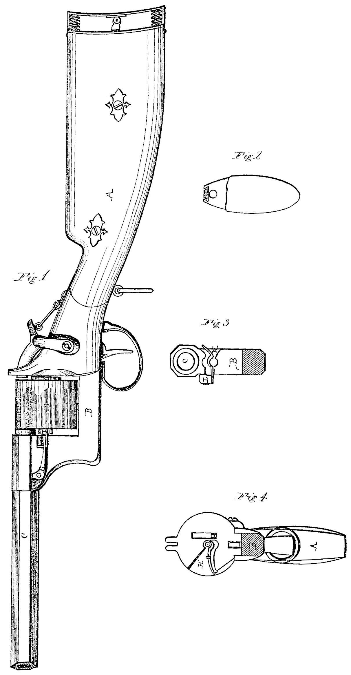
Figure 1 is a side elevation of my gun complete in its connection with the patent granted March 30, 1869. Fig. 2 is a section view, showing one of the springs by which the cylinder is held in place. Fig. 3 is another vertical section, showing the second spring for holding the cylinder.
Letter A represents the stock of my gun, from the front end of which extends an arm, B, through the top of which the barrel C is secured in position by means of a screw-thread. This arm is an extension of the stock, and may be formed of any desired material. In the space thus formed between the barrel C and the stock or breech A the cylinder D is placed. The construction of the cylinder will be here in after described.
In the front end of the breech is a gain or recess, H, extending from one side to and a little beyond the center, and in this recess is placed a spring, G, secured at the outer end and extending along and a short distance above the lower edge of the recess. At its inner end the spring G is bent or shaped so as to form a journal-bearing in which the journal on the rear end of the cylinder is to rest.
Across the inner side of the upper end of the arm B is another gain or recess, K, extending from side to side, and having in the center of its lower edge the lower half of a journal-bearing, formed as seen in Fig. 3, in Which the journal in the front end of the cylinder D rests.
On the side of the upper end of the arm B is secured a spring, L, which extends into and across the recess K, and is suitably bent up Ward, so as to form the upper half of the journal-bearing and hold the journal down.
The cylinder ID is on its rear end provided with an annular shoulder or projection, O, of such thickness that when the cartridges are placed in the cylinder it shall form an even surface with the heads of the cartridges, and consequently prevent the recoil of the cylinder from setting off the other cartridges.
On the front end of the cylinder is another similar projection, P, which I prefer making of a lesser diameter, but thicker, than the projection O. It should be of the same thick ness as the distance the barrel C projects to the rear of the upper end of the arm B.
From the center of both projections O and P journals project, which journals are inserted into the recesses HK in the journal-bearings formed therein.
The springs G and L are sufficiently strong to hold the cylinder firmly in place, and yet are so constructed that a slight blow from the hand on the side of the cylinder or a slight pull will release the cylinder from its position. The cylinder can be as readily replaced.
From the relative thicknesses of the two projections O and P it will be observed that it is impossible to insert the cylinder wrong. It must go in the right way. It cannot be inserted any other way.
Having thus fully described my invention, what I claim as new, and desire to secure by Letters Patent, is—
1. The cylinder D, constructed as described, with two circular shoulders or projections, O and P, of different thicknesses, one at each end, each of said projections having a journal, substantially as and for the purposes herein set forth.
2. The gains or recesses H and K, constructed as described, and for the purposes set forth.
3. The springs G and L, constructed as described, and for the purposes set forth.
4. The combination of the gains or recesses H K and springs G. L, all constructed as described, and for the purposes set forth.
5. The combination and arrangement of the breech A, arm B, barrel C, cylinder D, springs G L, recesses H K, and projections O P, all substantially as and for the purposes set forth.
In testimony that I claim the foregoing. I have hereunto set my hand this 12th day of July, 1869.
JOHN C, MILLER.
Witnesses:
F. Lehmann,
Wm. H. Mason.