
US 432369
UNITED STATES PATENT OFFICE.
JOHN CARTER AND WILLIAM JOHN WHITING, OF BIRMINGHAM, ENGLAND,
ASSIGNORS TO THOMAS WILLIAM WEBLEY AND HENRY WEBLEY, OF SAME PLACE.
REVOLVER.
SPECIFICATION forming part of Letters Patent No. 432,369, dated July 15, 1890.
Application filed March 14, 1889, Serial No. 303,311. (No model). Patented in England April 18, 1888, No. 5,778, and in Belgium January 31, 1889, No. 63,294.
To all whom it may concern:
Be it known that we, JOHN CARTER and WILLIAM JOHN WHITING, pistol-action filers, subjects of the Queen of Great Britain, and residing at Bracebridge Street, Astonjuxta, Birmingham, England, have invented certain new and useful Improvements in Revolvers and other Repeater Small-Arms, (for which applications have been made in Great Britain, dated the 18th day of April, 1888, No. 5,778, and in Belgium, dated the 31st day of January, 1889, initial No. 63,294;) and we do hereby declare the following to be a full, clear, and exact description of the invention, reference being had to the accompanying drawings, which for part of this specification.
This invention relates to revolvers and other like repeater small-arms, as hereinafter described.
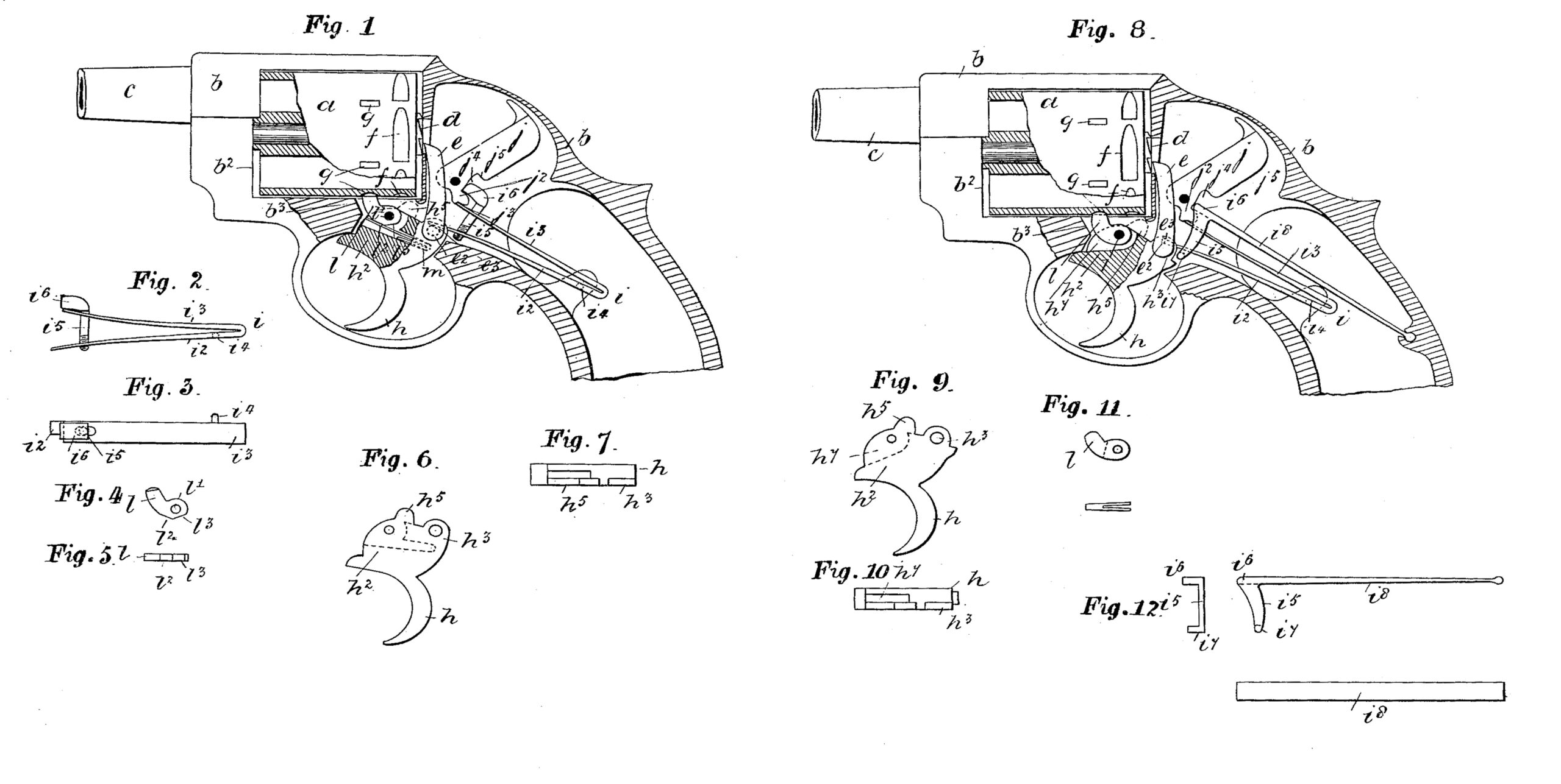
Figure 1 represents, partly in vertical section and partly in elevation, a solid-frame concealed-hammer revolver with a free moving cylinder constructed and arranged according to our invention. Fig. 2 is a front elevation of the spring and stay. Fig. 3 is a plan view of the same. Fig. 4 is an elevation, and Fig. 5 is a plan view, of the second cylinder-stop. Fig. 6 is a side view of the trigger, and Fig. 7 a top view of the same. Fig. 8 is a side view, partially in section, of a modified construction of fire-arms embodying our invention. Fig. 9 is a side view of the trigger. Fig. 10 is a top view of the same. Fig.11 is a side view of the second cylinder-stop, and Fig. 11a a plan view of the same. Fig. 12 is an end view, Fig. 13 a side view, and Fig. 14 a top view of the stay.
a is a chambered and free-working cylinder turning upon a central axis and moving within the rectangular-shaped recess b2 of the solid frame b, whose stock, furniture, and trigger-guard are made in one piece with it, while the fore part carries a barrel c, whose bore becomes coincident with the chambers of the free cylinder when the same is rotated for the bringing of its chambers into position for firing. The chambered cylinder has a centrally-disposed ratchet-faced annulus d at the middle of its rear end, and with the teeth of which said annulus the upper end of a lifter e engages.
The cylinder a has double-stop recesses f g, with which cylinder-stops h5 l engage. The stop h5 is an upper extension of the trigger-blade h2 of the trigger h, while the stop l, which is an upwardly-directed arm, turns upon a pivot or axis l’, common to both stop and trigger. The under side of the stop l has facets or flats l2 l3, upon which the free end of a spring m takes its bearing.
The lifter e is jointedly connected to the rear top side h3 of the trigger-blade h2 by an outstanding arm e2, with a flat e3 at its top side, upon which the free end of the stand-side limb of the mainspring takes its bearing.
The mainspring, which is marked i, has a threaded stay i5, with its lower shank end fixedly secured to the stand-side limb i2, while the upper end of the said shank passes loosely through an eye i7 near the end of the top limb i3 of the said spring. The upper end of the said stay has a head i6, which works within a gap j4 at the rear lower side of the hammer j, whose extreme lower part has a heel or short arm j2, with a bent or notch j3 made in its under side, and wherein the extreme free end of the limb i3 of the spring i engages when the hammer is at cock, and upon the under side of which said heel the free end of the spring presses rearwardly of the joint for throwing the hammer forward on the discharge of the arm. The stem of the stay i5 works freely, as aforesaid, through a hole in the top limb, so that on the lower limb, which rests upon the flat e3 of the arm e2 of the lifter e, rising by the upward movement of the trigger-blade the stay which is carried by the limb of the spring moves with it.
The action of the arm is as follows: The pulling of the trigger turns it rearward upon its pivot or center and takes the second cylinder-stop l from out of the second cylinder-stop recess g, and also raises the lifter e, which turns the cylinder round upon its axis to the extent of a chamber, and with the bore of the said chamber coincident with that of the barrel, and when in this position—viz., ready for firing—the first cylinder-stop h5 has passed into a first cylinder-stop recess f, and the second cylinder-stop l has fled back (as hereinafter described) into the second cylinder-stop recess f g, so that the cylinder is held at two points during firing. From this it will be seen that the cylinder during firing is held at two points and at other positions (save when rotating) at one, and the holding at one point is to prevent the cylinder rotating by itself or without action when a portion of the chambers are discharged. Thus the pulling of the trigger takes the No. 1 cylinder-stop from its recess, (which flies back again after a certain movement,) raises the lifter, and takes the other cylinder-stop into its recess after the lifter has turned the cylinder to the desired extent, and, further, the lifter in rising causes its arm e2 to compress and lift the lower limb i2 of the spring i, and so thereby elevate the stay i5, so as to bring the head i6 thereof upon the top side or shoulder j5 of the recess j4 of the hammer j, and there exert pressure upon the back of the hammer, which levers the extreme end of the limb i3 from out of the bent j3 of the arm j2 and brings the full force of the spring upon the heel or arm rear of the joint-pin, which throws the hammer, strikes the detonate of the cartridge, and then rebounds on pressure being relieved from the said trigger. The rebounding of the hammer is effected by the trigger resuming its normal position by the spring’s pressure exerted upon it, which causes the head of the stay, which is drawn downward, to be brought upon the top side of the heel or arm j2, so as to turn the hammer back to cock, which is caught and retained there by the end of the spring which engages with the bent.
The following is a further elucidation of the action of the cylinder-stops: The function of the stops is to hold the cylinders at two points and at one point on the return of the trigger. The No. 2 stop consists of a jointed limb l, turning upon the same pin as the trigger and with an abutment b3, against which it comes and rests on the first pulling of the trigger, and from which it again recedes to its normal position within the No. 2 cylinder-stop recess on the said trigger being fully pulled home. The under side of the stop has flats l2 l3, upon which the free end of a spring m respectively takes on the trigger changing its position. Thus the initial pulling of the trigger carries the stop l with it until its curved front part rests against the abutment b3, when the continued movement of the trigger and spring takes the free end of the said spring from the flat l’ to the flat l2, which thereby causes the stop to fly back into its original position; and, further, the return of the trigger on pressure being relieved from it allows the trigger to be returned to its normal position and the spring to again take upon the flat l’ of the stop l, as represented in Fig. 1.
a is the free-moving cylinder, turning upon a pivot-axis and working within a rectangular-shaped recess or opening b2 of a solid frame b, whose rear body part is gapped and wherethrough the upper end of the lifter e works and presses the cylinder round for bringing the respective chambers coincident with the bore of the barrel, as aforesaid. The lifter’s lower end is jointedly connected to the rear top side h3 of the trigger-blade h2, as before, by the arm e2, while the stay i5 is hooked at its lower end and marked i7; and upon which hooked part the free end of the standside limb i2 of the mainspring i rests, so that the turning rearwardly of the trigger by pulling the shoulder h6 thereof presses upward the said spring-limb and stay together, which causes the head i6 to come against the shoulder j5 of the gap j4 of the hammer j, as before. The stay i5 has an inflexible rod i8 for the keeping of the same in position.
The pulling of the trigger raises the lifter, takes the stop l out of the stop-recess g and the stop h5 into the stop-recess f, lifts the stay i5, and compresses the spring i, causes the head of the stay to press itself upon the rear of the hammer, so as to lever the end of the top side limb out of the bent, which when relieved causes the hammer to fall. The releasing of the trigger allows the parts to resume their normal positions and the stop l to again pass into its cylinder-stop recess g. Thus the cylinder-recess stop l is forked at its lower end and adapted to bind within a recess h7 of the trigger-blade, so that on the trigger being pulled this said stop is taken out of the cylinder-recess g, and on coming against the abutment b3 it is there retained until the return of the trigger, when they both again move together.
In this modification the arm on firing is only held by one cylinder-stop—viz., h5—and when in its normal position, as in Fig. 8, it is held by the second cylinder-stop l. Thus it will be observed that the said cylinder-stop l is carried to and fro by its forked parts binding within the recess h6 of the trigger.
Having thus described our invention, we claim as new and desire to secure by Letters Patent—
1. In a concealed-hammer revolver, the combination, with the frame-abutment b3 and a cylinder having two series of stop-recesses f g, of a trigger h, provided with stops h5 l, and spring, said stop l being pivotally secured to said trigger and formed with facets l2 l3, whereby said cylinder is held at two points by the stops h5 l when the arm is being fired and but at one point when the trigger is normal.
2. In a concealed-hammer revolver, the combination, with the cylinder, hammer, and trigger, and the operating mechanism thereof, including the mainspring i, pivoted by one of its leaves to the frame of the revolver, of a hook-headed stay i5 i6, located at the back of the hammer, secured to the lower leaf of the mainspring, and constructed and adapted to force the free end of the spring from the bent on the lower end of the hammer and to throw the hammer forward, substantially as described.
3. In a concealed-hammer revolver, the combination, with the cylinder, trigger, and mainspring, the latter being pivoted to the frame of the revolver, of the hammer j, having arm j3 and gap j4, and the stay i5 i6, attached to the lower leaf of said spring and engaging with said hammer, substantially as described.
4. In a concealed-hammer revolver, the combination, with the cylinder, trigger, hammer, and mainspring, the latter being pivoted by one of its leaves to the frame of the revolver, of the stay i5 i6, attached to the lower leaf of the mainspring and engaging with the hammer, substantially as described.
In testimony that we claim the foregoing we have hereunto set our hands.
JOHN CARTER.
WILLIAM JOHN WHITING.
Witnesses:
HENRY SKERRITT,
MILES E. HUGHES,
Both of Birmingham.