
US 37059
UNITED STATES PATENT OFFICE.
JAKOB RUPERTUS, OF PHILADELPHIA, PENNSYLVANIA.
IMPROVEMENT IN REVOLVING FIRE-ARMS.
Specification forming part of Letters Patent No. 37,059, dated December 2, 1862.
To all whom it may concern:
Be it known that I, J. RUPERTUs, of Philadelphia, Pennsylvania, have invented certain Improvements in Revolving Fire-Arms; and I do hereby declare the following to be a full, clear, and exact description of the same, reference being had to the accompanying drawings, and to the letters of reference marked thereon.
My improvements consist, first, in a center-pin having one end secured to the barrel and the other end formed so as to fit to the frame, substantially in the manner described hereinafter, the pin thereby serving as a longitudinal stay for stiffening the frame; secondly, in a device for locking the said center-pin to the frame.
In order to enable others skilled in the art to make and use my invention, I will now proceed to describe its construction and operation.
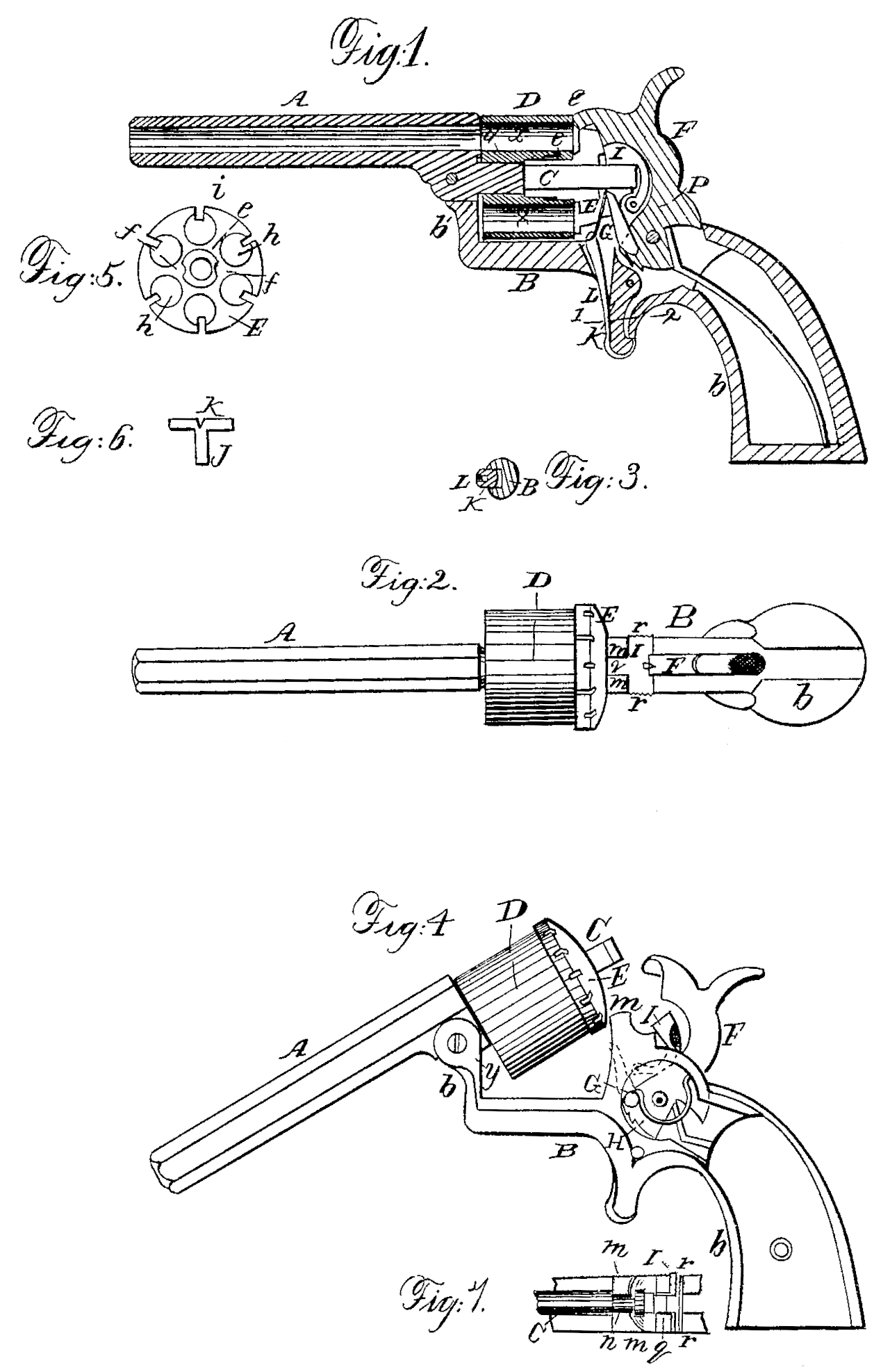
On reference to the accompanying drawings, which form a part of this specification, Figure 1 is a longitudinal section of my improved revolving fire-arm; Fig. 2, a plan view; Fig. 3, a transverse section on the line 12, Fig. 1; Fig. 4, an exterior view of the fire-arm with a portion removed; Fig. 5, an inside view of the cap of the cylinder; Fig. 6, an enlarged view of the end of the hammer, and Fig. 7 a plan view of part of Fig. 4.
Similar letters refer to similar parts throughout the several views.
A represents the barrel, and B the frame, of my improved revolving fire-arm, the continuation b of the frame forming the handle or stock.
C is the breech or center pin, which is secured to or forms a part of the barrel, and on which fits the cylinder, the latter in the present instance having six chambers, x, and consisting of two pieces, D and E, the piece D being the cylinder proper and the piece E the cap or cover. As the peculiar construction of this cylinder forms the subject of a separate application for a patent, it will be unnecessary to describe it minutely here.
At the rear of the cap E is a circular rack, such as is commonly used on the cylinders of revolving fire-arms, and into the inclined teeth of this rack engages the point of the dog or pawl G, which is jointed to the hammer F, the dog being maintained in proper contact with the rack by a spring, H, which is composed of a simple piece of steel wire bent to the form represented in Fig. 4, one end of the wire fitting into a recess in the frame and the other end into a recess in the dog, the spring being in contact with no other points, and being consequently free from all friction and liability to wear.
A curved arm, I, is hinged to the frame B at p, the rear of the arm being made of a shape to conform with that of the hammer. The outer end, 1, of this arm is arranged to fit snugly in the space between the projections m m of the frame B. (See Fig. 7.) The arm, at a short distance from its outer end, has two lateral projections, r r, so situated that the operator can, with his finger and thumb applied to the roughened ends of these projections, readily move the arm backward and forward.
It will be seen, on reference to Fig. 7, that the center-pin C, near its outer end, is contracted by cutting away a portion on each side, so that the contracted portion of the pin may fit into the space i between the two projections m m of the frame.
The trigger K, which, as regards its connection with the hammer, is similar to the triggers of ordinary revolvers, has a slot or recess in front for the reception of a spring, L, the end of which is arranged to fit into the slots i of the cap E, thereby retaining or steadying the cylinder in its proper position and insuring the coincidence of each chamber in succession with the bore of the barrel.
The barrel, with its center-pin, is hinged to the projection b’ of the frame by means of the pin y, so that the outer end of the barrel may be depressed and the breech-pin elevated, as seen in Fig. 4.
It will be readily seen by all familiar with revolving fire-arms that by making the center pin a part of the barrel, and by hinging the whole to the frame in the manner described, a more ready means of removing the cylinder from and connecting it to the fire-arm is obtained than by the use of the ordinary detachable center-pin. After the cylinder has been adjusted to the center-pin the latter is depressed, its contracted portion fitting between the two projections m m of the frame, after which the bent arm I is moved forward from the position shown in Fig. 4 to that seen in Fig. 1, so as to fit between the projections m m and over the center-pin. Not only is the latter thus held firmly, but it serves as a longitudinal stay for stiffening the frame at the point where it would be otherwise weak.
I claim as my invention and desire to secure by Letters Patent—
1. The center – pin C, having one end secured to the barrel and the other end formed, substantially as described, so as to fit to the frame, the pin thereby serving as a longitudinal stay to stiffen the said frame, as described.
2. The arm I, hung to the frame and adapted to the end of the center-pin, substantially as described.
In testimony whereof I have signed my name to this specification in the presence of two subscribing witnesses.
JAKOB RUPERTUS.
Witnesses:
Henry Howson,
John White.