
USA 7802
UNITED STATES PATENT OFFICE.
JOSHUA STEVENS, OF CHICOPEE, MASSACHUSETTS.
IMPROVEMENT IN LOCKING APPARATUS OF REPEATING FIRE-ARMS.
Specification forming part of Letters Patent No. 7,8022, dated November 26, 1850.
To all whom it may concern:
Be it known that I, Joshua Stevens, of Chicopee, in the county of Hampden and State of Massachusetts, have invented certain new and useful Improvements in Repeating Fire-Arms; and I do hereby declare that the same are fully described and represented in the following specification and accompanying drawings, letters, figures, and references thereof.
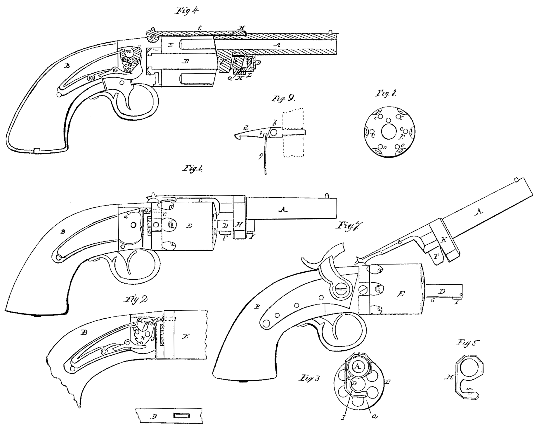
Of the said drawings, Figure 1 represents a side view of one of my improved repeating-pistols as it appears when the lock is removed. Fig. 2 is a view of the inside of the lock. Fig. 3 is an end view of said pistol, representing the muzzle and certain parts to be hereinafter described. Fig. 4 is a longitudinal central and vertical section. Fig. 5 is a side view of the contrivance by which the barrel is confined to the spindle on which the many-chambered cylinder revolves. Fig. 6 is an under side view of the end of said spindle. Fig. 7 represents a side view of the whole pistol, the barrel being represented as elevated or thrown upward into such a position as will enable a person to readily remove the chambered cylinder from the spindle.
In the said drawings, A represents the barrel of the repeating-pistol, which is connected to the stock or handle B by an arm, C, which extends backward from it, and is hinged to the stock in such manner as to permit the barrel to be freely raised upward and downward.
From the stock the spindle D extends outward underneath the barrel, as seen in the drawings, the many-chambered cylinder E being placed and made to revolve upon said spindle in a position as seen in the figures. From the lower part of the rear portion of the barrel a tenon, F, projects, and when the barrel is moved downward said tenon enters into a corresponding mortise, G, made through the spindle directly in front of the chambered cylinder, the tenon and mortise serving to prevent lateral motion of the barrel during a discharge, such lateral motion being likely to affect the correct action of the clamping contrivance, to be described.
The contrivance for holding the barrel down or confining it to the spindle while the pistol is being fired consists of a hooked piece of metal, H, formed as seen in the drawings and placed and made to freely revolve upon the barrel in the position as seen in the drawings. This hook or clasp, when turned around, is made to shut over or partly encircle or inclose the spindle, and is kept in place by means of a small Spring-catch, I, which is properly applied to the spindle and made to enter a small recess, a, made within the hook. When this Spring-catch is elevated and the hook turned around so as to not clasp the spindle the barrel may readily be elevated or raised into such an inclined position as to allow of the easy removal of the many-chambered cylinder.
In Fig. 1 of the drawings the small spring-bolt employed to hold the many-chambered cylinder in position during each discharge of its chambers is seen at b. It is arranged in the upper part of the stock or lock case, and operates in connection With a series of small holes or recesses, c c c, &c., made in the rear of the many-chambered cylinder in the position as denoted in Fig. 8, which denotes a view of the rear end of the said cylinder.
To the rear end of the small slide-bolt b a small dog or catch-hook, d, is hinged or jointed, so as to be capable of playing freely up and down in a vertical direction. The said catch (a side view of which and the bolt is represented on an enlarged scale in Fig. 9) has a square recess, i, formed upward in its under side and just in rear of its front end. Against the front side of this recess a spring, d, is made to bear, the lower end of said spring being fastened in position. The recess i of the catch should have that part of it against which the spring bears so formed that the spring, when the catch-hook is not in action with the tumbler of the cock, shall cause the catch-hook to take an inclined position, or, in other words, to cause said hook, When the cock is thrown forward, to catch upon or engage with the part m of the tumbler n of the cock.
In connection with the shoulder or part on, the tumbler is made cam-shaped at o for the purpose of elevating the hook from the shoulder during the time the cock is being drawn back, and this for the purpose of allowing the bolt to move or be thrown forward by the spring. Whenever the bolt is drawn back a peculiar mechanism is put in operation for the purpose of causing a partial rotation of the many-chambered cylinder. Before the chambered cylinder can be so rotated the little bolt b, must be retracted far enough to move its front end out of that recess c in which it may be. The said bolt must be held back or kept retracted during such time as the cylinder is being partially rotated. Such partial rotation of the cylinder having taken place, the cam on the tumbler of the cock immediately elevates the dog or catch so far above the shoulder of the tumbler as to allow the little bolt to be freely thrown forward by the reaction of its spring. From the above it will be seen that the said spring performs two functions, one of which is to throw the bolt forward, while the other is to depress the catch.
Now, in pistols of this kind as heretofore constructed the dog or catch has not been hinged or jointed to the bolt, but has been firmly fixed to it, and in consequence thereof has required for its operation two springs and certain complicated mechanism which is done away with by my improvement.
My improvement, and what I claim as my invention, consists—
In hinging the dog or catch to the bolt, in combination with so making and applying the recess i and the spring g together and to the dog or catch as to cause said spring to perform two functions, or to not only operate the dog or catch, but to operate the bolt, essentially in the manner as above described.
In testimony whereof I have hereto set my signature this 7th day of October, A.D. 1850.
JOSHUA STEVENS.
Witnesses:
A. P. Whitehouse,
E. V. B. Holcomb.